

Nondestructive testing
When dense porosity is found in nondestructive testing (especially UT), it is a very typical and serious quality problem. Systematic root cause analysis is crucial to avoid arbitrary conclusions and unnecessary rework.Nondestructive testing
Below is a systematic investigation framework that you can address one by one from six aspects: people, machines, materials, methods, environment, and testing, following the principle of starting with the easiest and progressing to the most difficult, and from the surface to the core.
Step 1: Nondestructive testing,Preliminary Investigation and Information Gathering
Before starting the investigation, gather as much information as possible to lay the foundation for analysis:
❶ Defect Morphology: The specific appearance of porosity on the UT (amplitude, density, distribution), and its location in the weld (arc initiation/arc termination, weld overlap, root/cap).
❷ Welding Records: Specific welding procedure specifications (WPS/PQR), welder information, welding date and time period, and welding material batch number.
❸ Base Material Information: Base material material, specifications, and furnace batch number.
❹ Historical Situation: Has a similar problem occurred before? Is it an occasional occurrence or a frequent one?
Step Two: Investigate one by one according to six aspects
❶ Personnel Operation
⑴ Welder Skills and Awareness:
● Is the welder certified and does their certification cover the current welding task?
● Does the operation comply with the Welding Procedure Specification (WPS) requirements? In particular:
a. Arc length control: An excessively long arc will lead to insufficient shielding gas coverage and air intrusion.
b. Welding speed: Too fast a speed will cause the molten pool to solidify quickly, and the gas will not have enough time to escape.
c. Welding torch angle: An improper angle (such as excessive tilt) will damage the shielding gas cover.
d. Arc starting and ending operation: Improper arc starting and ending techniques can easily produce porosity.
⑵ Training and Supervision: Has the welder received sufficient training on preventing porosity? Is there sufficient supervision on site?
❷ Equipment and Tools
⑴ Gas supply system: This is the most common cause of dense porosity.
● Gas purity: Is the purity of the shielding gas (such as Ar, CO₂) up to standard? (Check quality certificates).
●Gas Line Leaks: Is there any leakage in the entire gas line (hose, connectors, valves) from the gas cylinder to the welding torch? Check for leaks with soapy water.
●Flow Rate Settings: Is the gas flow rate appropriate? Too low a flow rate results in poor protection; too high a flow rate creates turbulence and draws in air.
●Accessory Issues: Is the welding torch nozzle too large, too small, or clogged? Is the gas lens clean? Does wear on the contact tip cause arc instability?
⑵ Wire Feeding System:
●Is the wire feeding smooth and stable? Poor wire feeding can cause arc fluctuations and molten pool disturbances.
●Is the wire feed roller pressure appropriate? Is the wire guide tube clean and free of wear?
⑶Welding Power Supply: Is the power output stable? Fluctuations in voltage and current can affect the stability of the molten pool.
❸Welding Materials
⑴Welding Wire/Electrode:
●Is the model and specification correct?
●Is it damp, rusty, or contaminated with oil or moisture?
●For flux-cored wire, is the core powder damp? (Usually controlled through a baking process)
⑵ Shielding Gas:
● Is the gas composition correct?
● Is the pressure inside the gas cylinder too low, leading to decreased gas purity or air contamination?
⑶ Base Material:
● Is the bevel and its surrounding area (10-20mm on both sides) clean? Are there any rust, oil, paint, or moisture? This is another very common cause.
● For some steels (such as high-strength steel), the surface coating (such as a zinc layer, from galvanized sheet) may vaporize during welding, creating porosity.
❹ Process Method
⑴ Welding Procedure Specification:
● Are the WPS parameters reasonable? The matching of voltage, current, and speed needs to be reviewed.
● Are parameters such as gas flow rate and preheating temperature (if any) set within the specified range?
● For thick plates or multi-layer, multi-pass welding, is the interpass temperature properly controlled? Excessive temperature may cause impurities between weld passes to concentrate and generate gas.
⑵ Bevel Design: A bevel angle that is too small may cause poor shielding gas flow at the root, forming gas pockets.
❺ Environmental Conditions
⑴ Wind Speed: In outdoor welding or well-ventilated areas, excessive wind speed can disperse the protective gas. Generally, wind speed < 2 m/s is required.
⑵ Humidity: High ambient humidity can cause moisture in the air to decompose into hydrogen gas under the high temperature of the electric arc, leading to hydrogen porosity.
⑶ Temperature: Low temperatures may cause condensation on the base material surface, introducing moisture.
❻ Inspection Process
⑴ UT Operation Itself:
● Are the inspection personnel qualified?
● Is the UT equipment effectively calibrated?
● Is the coupling agent sufficient and is the coupling effect good?
● Are there any misjudgments? Dense porosity on the UT usually appears as dense clusters of echoes, with low amplitude but continuous occurrence. Sometimes, comparison and verification with other non-destructive testing methods (such as RT) are necessary.
⑵ Acceptance Criteria: Are the acceptance criteria used (such as ISO 5817, AWS D1.1) correct? Is the porosity level assessment accurate?
Step 3: Analysis and Verification
After completing the above investigation:
❶ List the most likely root causes: Based on the density and location of the porosity, prioritize investigating the most common causes. For example, if it affects the entire weld seam, prioritize systemic factors such as gas, welding materials, and the environment; if it is localized, prioritize local cleaning and improper operation.
❷ Conduct comparative tests: On the test piece, keep other conditions constant and change only one suspected variable (such as reducing welding speed, cleaning the bevel more thoroughly, or replacing the gas cylinder) to see if the porosity disappears.
❸ Metallographic analysis: If conditions permit, take samples from the defect location for metallographic analysis. This is the most direct method, allowing you to dissect the pores and observe their internal morphology, sometimes providing clues about the gas source (e.g., hydrogen pores usually have smooth inner walls, while carbon monoxide pores may have rougher inner walls).
Summary:Nondestructive testing, Investigation Checklist
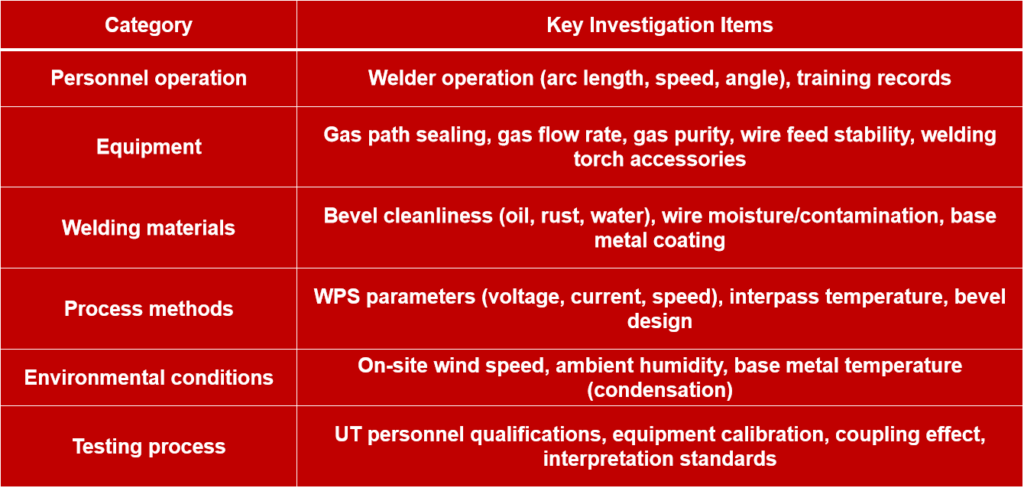
Through the above systematic investigation, the root cause of most porosity problems can be located. The key is to be logical, step-by-step, and evidence-based, avoiding blind “trial and error”.