

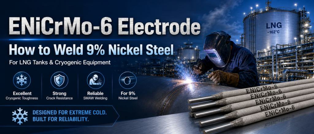
How to Weld 9% Nickel Steel with ENiCrMo-6 Electrodes
Nine-percent nickel steel is widely used in liquefied natural gas storage tanks and other cryogenic equipment because it retains high strength and toughness at extremely low temperatures. However, producing a reliable welded joint requires more than choosing a strong base material.ENiCrMo-6
The weld metal must also maintain adequate toughness, ductility, strength, and resistance to cracking under cryogenic service conditions. ENiCrMo-6 electrodes are specifically designed for shielded metal arc welding of 9% nickel steel and other low-temperature materials.
Their nickel-chromium-molybdenum alloy weld deposit provides excellent cryogenic toughness and a thermal expansion behavior that is compatible with 9% nickel steel. These characteristics make ENiCrMo-6 electrodes suitable for LNG tanks, low-temperature pressure vessels, storage systems, and cryogenic process equipment.
This guide explains how to weld 9% nickel steel with ENiCrMo-6 electrodes, covering material preparation, electrode handling, joint design, welding parameters, heat-input control, defect prevention, and inspection.
ENiCrMo-6 What Is 9% Nickel Steel?
Nine-percent nickel steel is a low-carbon alloy steel containing approximately 9% nickel. The addition of nickel improves toughness and resistance to brittle fracture at very low temperatures.
This material is commonly used in equipment that stores or processes liquefied gases, including:
Liquefied natural gas storage tanks
Cryogenic pressure vessels
Low-temperature process equipment
Liquefied gas transportation systems
LNG terminal equipment
Cryogenic piping components
Storage systems operating near −196°C
Although 9% nickel steel offers excellent low-temperature performance, the heat-affected zone and weld metal must be carefully controlled during fabrication. Excessive heat input, moisture, contamination, poor bead placement, or incorrect consumable selection can reduce weld quality.
What Is an ENiCrMo-6 Electrode?
ENiCrMo-6 is a nickel-chromium-molybdenum covered electrode classified under AWS A5.11 for shielded metal arc welding.
The corresponding EN ISO classification is generally E Ni 6620, indicating a nickel-based weld deposit containing chromium, molybdenum, iron, and other controlled alloying elements.
ENiCrMo-6 electrodes are primarily used for:
Welding 9% nickel steel
Welding 5% nickel steel
Fabricating LNG storage tanks
Joining low-temperature and cryogenic steels
Welding selected nickel alloys
Producing dissimilar-metal joints
Repairing cryogenic process equipment
Applying nickel-alloy buffer layers
The deposited weld metal is designed to maintain toughness at cryogenic temperatures while providing suitable strength and crack resistance.
Why Use ENiCrMo-6 for 9% Nickel Steel?
Selecting the correct welding consumable is essential because an ordinary steel electrode may not retain adequate toughness at LNG service temperatures.
ENiCrMo-6 offers several advantages when welding 9% nickel steel.
Excellent Cryogenic Toughness
The nickel-rich weld deposit remains ductile at extremely low temperatures. This helps the completed joint resist brittle fracture during filling, storage, operation, and thermal cycling.
Compatible Thermal Expansion
ENiCrMo-6 weld metal has a coefficient of thermal expansion that is relatively close to that of 9% nickel steel. This compatibility helps reduce thermally induced stresses when equipment cools from ambient temperature to cryogenic operating conditions.
High Resistance to Weld Cracking
The nickel-based weld deposit provides strong resistance to hot cracking, stress-related cracking, and thermal shock when the welding procedure is properly controlled.
Suitable Strength
ENiCrMo-6 weld metal can provide the strength required for structural joints in LNG tanks and cryogenic vessels. However, the final properties depend on electrode selection, dilution, welding position, heat input, and procedure qualification.
Good All-Position Capability
Many ENiCrMo-6 electrodes are developed for flat, horizontal, vertical, and overhead welding. This is important in large LNG tank construction, where welds must be completed in several positions.
ENiCrMo-6 Standards and Material Identification
Before welding begins, confirm the exact grade and condition of the base material.
Common 9% nickel steel specifications may include materials produced to standards such as:
ASTM A353
ASTM A553 Type I
Equivalent national or project specifications
Quenched-and-tempered 9% nickel steel grades
Material identification should be verified through mill certificates, traceability records, and positive material identification when required.
The welding electrode should comply with the classification, mechanical-property, packaging, and project requirements listed in the approved welding procedure.
Do not assume that every nickel-alloy electrode is suitable for 9% nickel steel. ENiCrMo-3, ENiCrFe classifications, and other nickel-based consumables may have different mechanical properties, thermal expansion behavior, and operating characteristics.
ENiCrMo-6 Preparing 9% Nickel Steel for Welding
Proper preparation has a major influence on weld soundness and cryogenic performance.
Clean the Joint Thoroughly
Remove all contaminants from the groove and surrounding surfaces, including:
Oil
Grease
Paint
Moisture
Rust
Mill scale
Cutting residue
Dirt
Sulfur-containing compounds
Temporary marking materials
Clean both sides of the joint and a sufficient distance beyond the groove. Contamination can cause porosity, inclusions, cracking, and unstable arc behavior.
Use clean grinding wheels, files, and brushes dedicated to nickel-alloy and cryogenic-steel work. Tools previously used on carbon steel may introduce unwanted particles.
Use Accurate Joint Preparation
The joint geometry should follow the qualified welding procedure. Important details include:
Groove angle
Root face
Root opening
Plate alignment
Back-gouging requirements
Temporary backing method
Tack-weld arrangement
A groove that is too narrow can restrict electrode access and increase the risk of lack of fusion or slag entrapment. An excessively wide groove increases weld volume, heat input, consumable use, and distortion.
Check Fit-Up and Alignment
Poor alignment can create uneven root penetration and local stress concentration. Use suitable fixtures, strongbacks, or temporary attachments to maintain the specified joint position.
Temporary attachments should be made from approved materials and welded using an accepted procedure. They must be removed without damaging the base material.
ENiCrMo-6 Prepare Tack Welds Correctly
Tack welds should be deposited by qualified welders using approved consumables and parameters. Defective tack welds must be completely removed before production welding.
Tacks incorporated into the final joint should be ground to a smooth profile to ensure complete fusion.
ENiCrMo-6 Electrode Storage and Handling
Covered nickel-alloy electrodes must remain dry. Moisture in the coating can lead to porosity, unstable arc behavior, poor slag control, and weld defects.
Store ENiCrMo-6 electrodes:
In sealed original packaging
In a clean and dry storage area
Away from water and condensation
At a controlled temperature
According to the electrode manufacturer’s instructions
Cold packages should be allowed to reach the welding-area temperature before opening. Opening a cold package in a warm, humid area can cause condensation on the electrodes.
Once the package is opened, transfer electrodes to an approved heated holding container when required by the procedure.
Do not use a general rebaking temperature without checking the electrode instructions. Excessive rebaking can damage the coating, while insufficient drying may fail to remove absorbed moisture.
Electrodes with cracked, damaged, contaminated, or badly moisture-saturated coatings should be discarded.
ENiCrMo-6 Selecting the Correct Electrode Diameter
Electrode diameter affects deposition rate, heat input, positional capability, and access to the joint.
Smaller electrodes are commonly selected for:
Root passes
Vertical welding
Overhead welding
Restricted joints
Thin sections
Areas requiring precise heat control
Larger electrodes may be used for:
Flat-position fill passes
Thick plate
High-deposition applications
Wide, accessible grooves
The selected diameter must be permitted by the qualified welding procedure. Larger electrodes should not be used simply to increase production speed if they cause excessive heat input or poor control of the weld pool.
ENiCrMo-6 Welding Polarity and Power Source
ENiCrMo-6 electrodes may be designed for direct current electrode positive, alternating current, or more than one polarity, depending on their coating formulation.
Always follow the electrode data sheet and qualified welding procedure.
A constant-current power source with stable arc characteristics is generally suitable for shielded metal arc welding. The welding cables, electrode holder, ground connection, and power source should be in good condition.
Unstable electrical connections can cause arc interruptions, inconsistent penetration, and weld defects.
ENiCrMo-6 Recommended Welding Technique
Maintain a Short Arc Length
Use a short, controlled arc. A long arc can increase:
Arc instability
Spatter
Oxidation
Heat input
Porosity risk
Undercut
Irregular bead shape
A short arc helps produce a more stable weld pool and improves control in positional welding.
Use Stringer Beads
Stringer beads are generally preferred for welding 9% nickel steel with ENiCrMo-6 electrodes.
Wide weaving can increase heat input and keep the weld pool molten for too long. This may reduce positional control and increase the risk of slag inclusions or an excessively wide heat-affected zone.
Limited weaving may be permitted when necessary, but the maximum weave width should be defined by the approved procedure.
Control the Electrode Angle
Maintain a consistent travel angle that supports the weld pool without allowing slag to run ahead of the arc.
An incorrect electrode angle may cause:
Slag entrapment
Incomplete fusion
Irregular penetration
Excessive reinforcement
Undercut
In vertical-up welding, use controlled bead placement and pause briefly at the sidewalls when required to achieve fusion.
Deposit Smaller, Controlled Beads
Nickel-alloy weld metal flows differently from carbon-steel weld metal. It may appear sluggish and may not spread as freely.
Do not increase current excessively in an attempt to make the weld pool flow faster. Instead, use suitable joint preparation, proper manipulation, and controlled bead size.
Fill the Crater
Do not break the arc abruptly and leave an unfilled crater. Crater cracks may develop as the weld pool solidifies.
Before stopping, reduce travel speed slightly and fill the crater. Use the approved restart technique when continuing the weld.
Controlling Heat Input
Heat-input control is one of the most important parts of welding 9% nickel steel.
Excessive heat input may:
Increase distortion
Produce a wider heat-affected zone
Reduce control of the weld pool
Encourage grain growth
Increase dilution
Affect cryogenic properties
Increase residual stress
Heat input is influenced by welding current, arc voltage, and travel speed. Welders should use the parameter range established in the qualified procedure rather than relying only on visual appearance.
Avoid slow travel with excessive current. Use consistent travel speed and smaller stringer beads to control the thermal cycle.
The welding engineer should define the permitted heat-input range based on procedure qualification results.
Preheat and Interpass Temperature
The required preheat depends on the plate specification, thickness, restraint, ambient conditions, hydrogen-control plan, and project code.
In many applications, heavy preheating of clean 9% nickel steel is not desirable. However, the joint must be dry and warm enough to prevent condensation.
Light warming may be used to:
Remove surface moisture
Keep the material above the dew point
Stabilize the joint temperature
Support hydrogen control
The interpass temperature must be monitored and kept within the approved procedure limit. Excessively high interpass temperature can increase accumulated heat input and affect weld properties.
Use calibrated contact thermometers, temperature crayons, or suitable electronic instruments to verify temperature.
Do not begin the next pass until the joint has cooled to the required range.
Root-Pass Welding
The root pass establishes penetration and alignment for the rest of the joint. Root defects can be difficult to remove after multiple passes have been deposited.
Before welding the root:
Confirm the root opening and alignment.
Clean the groove completely.
Verify that the electrode is dry.
Check the correct polarity.
Set the approved current range.
Ensure access to the full joint.
Confirm the required backing arrangement.
Use a short arc and maintain steady travel. Avoid excessive reinforcement, incomplete penetration, and abrupt starts or stops.
When welding from both sides, the root area may require back-gouging or grinding before welding the second side. Remove all slag, oxide, and defective metal until clean, sound material is exposed.
Fill and Cap Passes
Fill passes should be arranged to avoid narrow valleys and slag traps between beads.
Clean every pass before depositing the next one. Slag removal may require chipping, grinding, and brushing.
Inspect each layer for:
Cracks
Porosity
Undercut
Lack of fusion
Slag inclusions
Irregular bead profile
Excessive reinforcement
Repair defects immediately rather than covering them with additional weld metal.
The cap should have a smooth transition to the base material. Avoid excessive crown height, sharp toes, undercut, or an excessively wide cap.
A smooth weld profile improves inspectability and reduces local stress concentration.
Welding Positions in LNG Tank Construction
Large LNG storage tanks require several welding positions.
Vertical Joints
Vertical shell joints are commonly welded in the vertical-up direction. The welder must control slag movement and maintain fusion at both sidewalls.
Smaller electrodes and controlled stringer beads are often preferred.
Horizontal Joints
Horizontal circumferential joints require careful electrode positioning to prevent the weld pool from sagging. Bead sequence and electrode angle are especially important.
Overhead Joints
Overhead welding requires an electrode specifically approved for the position. Use a short arc, smaller weld pool, and carefully controlled current.
Not every ENiCrMo-6 product provides identical overhead performance, so positional qualification is essential.
Flat-Position Joints
Flat welding generally allows larger electrodes and higher deposition rates. Heat input must still remain within the qualified range.
Common Welding Defects and Prevention
Porosity
Porosity may be caused by:
Damp electrodes
Moisture on the plate
Oil or grease
Excessive arc length
Damaged electrode coating
Poor restart technique
Contaminated joint surfaces
Prevent porosity by keeping electrodes dry, cleaning the joint, maintaining a short arc, and following the approved storage procedure.
Slag Inclusions
Slag inclusions can result from:
Inadequate interpass cleaning
Narrow joint angles
Poor bead placement
Low welding current
Incorrect electrode angle
Excessive weaving
Remove slag completely and ensure that every bead fuses into the sidewall and adjacent weld metal.
Lack of Fusion
Lack of fusion may occur when:
Heat input is too low
Travel speed is too high
The joint is too narrow
The electrode angle is incorrect
The welder fails to direct the arc at the sidewall
Slag remains between passes
Correct the parameter balance and improve joint access rather than simply increasing current.
Undercut
Undercut may be caused by high current, long arc length, excessive travel speed, or poor electrode manipulation.
Reduce the arc length and use controlled travel with proper sidewall pauses when necessary.
Crater Cracking
Crater cracks form when the arc is stopped without filling the end of the weld pool.
Use a controlled termination method and grind out any visible crater crack before restarting.
Arc Strikes
Arc strikes outside the weld groove can create local hard spots or surface damage. Use insulated electrode holders and designated strike plates where permitted.
Unauthorized arc strikes should be examined and removed according to the project procedure.
Avoiding Magnetic Arc Blow
Residual magnetism can create arc blow during welding of large 9% nickel steel structures. Arc blow may cause unstable penetration, wandering arcs, undercut, and slag inclusions.
Methods for reducing arc blow include:
Changing the ground-clamp position
Using shorter arc length
Reducing welding current within the approved range
Altering welding direction
Using alternating current when approved
Demagnetizing the joint
Applying temporary magnetic-control techniques
Any corrective method must remain within the qualified welding procedure.
Post-Weld Heat Treatment
Post-weld heat treatment is not automatically required for every 9% nickel steel joint. Its use depends on the material specification, construction code, joint design, thickness, service requirements, and procedure qualification.
Unnecessary or incorrectly controlled heat treatment may affect base-metal properties or cause unwanted changes at the fusion boundary.
Do not apply post-weld heat treatment unless it is specifically required and supported by an approved engineering procedure.
ENiCrMo-6 Inspection and Testing
Cryogenic equipment requires strict weld-quality control because defects can become critical at low temperature.
Inspection may include:
Visual testing
Liquid penetrant testing
Magnetic testing where technically applicable
Radiographic testing
Ultrasonic testing
Leak testing
Hydrostatic or pneumatic testing
Tensile testing
Bend testing
Charpy impact testing
Fracture-mechanics testing
Chemical analysis of weld metal
The inspection method and acceptance criteria should follow the applicable construction code and project specification.
ENiCrMo-6 Procedure Qualification
A welding procedure specification should define:
Base-material grade
Base-material thickness
Joint design
Welding position
Electrode classification
Electrode diameter
Polarity
Current range
Voltage range where applicable
Travel speed
Heat-input range
Preheat temperature
Interpass-temperature limit
Bead technique
Back-gouging method
Electrode storage conditions
Inspection requirements
Procedure qualification should demonstrate that the completed weld satisfies mechanical-property and cryogenic-toughness requirements.
A successful room-temperature tensile test alone does not prove that the joint is suitable for LNG service. Low-temperature impact performance and other project-specific tests are also important.
ENiCrMo-6 Welder Qualification
Welders must be qualified for the process, material group, electrode type, joint type, thickness range, and welding position required by the project.
Before production begins, welders should practice with the selected ENiCrMo-6 electrode because nickel-alloy weld pools and slag systems behave differently from ordinary carbon-steel electrodes.
Production quality improves when welders understand:
The correct arc length
Slag behavior
Electrode manipulation
Restart technique
Bead placement
Heat-input limits
Positional characteristics
ENiCrMo-6 Practical Welding Checklist
Before welding:
Verify the 9% nickel steel grade.
Confirm the approved ENiCrMo-6 classification.
Review the qualified welding procedure.
Check electrode packaging and storage history.
Clean the joint and adjacent surfaces.
Verify groove dimensions and alignment.
Confirm polarity and current range.
Check preheat and interpass requirements.
Ensure inspection tools are available.
During welding:
Maintain a short arc.
Use controlled stringer beads.
Monitor heat input.
Keep within the interpass-temperature limit.
Remove slag after every pass.
Inspect each bead before continuing.
Fill all craters.
Prevent arc strikes outside the groove.
After welding:
Clean the completed joint.
Perform visual examination.
Remove unacceptable surface defects.
Complete required nondestructive testing.
Record welding parameters.
Maintain material and welder traceability.
Protect the joint from contamination and mechanical damage.
ENiCrMo-6 Conclusion
Learning how to weld 9% nickel steel with ENiCrMo-6 electrodes requires careful control of cleanliness, electrode condition, joint preparation, arc length, bead placement, heat input, and interpass temperature.
ENiCrMo-6 weld metal is well suited to cryogenic fabrication because it offers excellent low-temperature toughness, reliable strength, resistance to cracking, and thermal expansion behavior compatible with 9% nickel steel.
However, the electrode classification alone cannot guarantee weld quality. Successful LNG tank and cryogenic-equipment fabrication depends on a qualified welding procedure, trained welders, dry consumables, controlled parameters, complete slag removal, and thorough inspection.
By following these practices, fabricators can produce strong and reliable 9% nickel steel welds for demanding low-temperature service.