
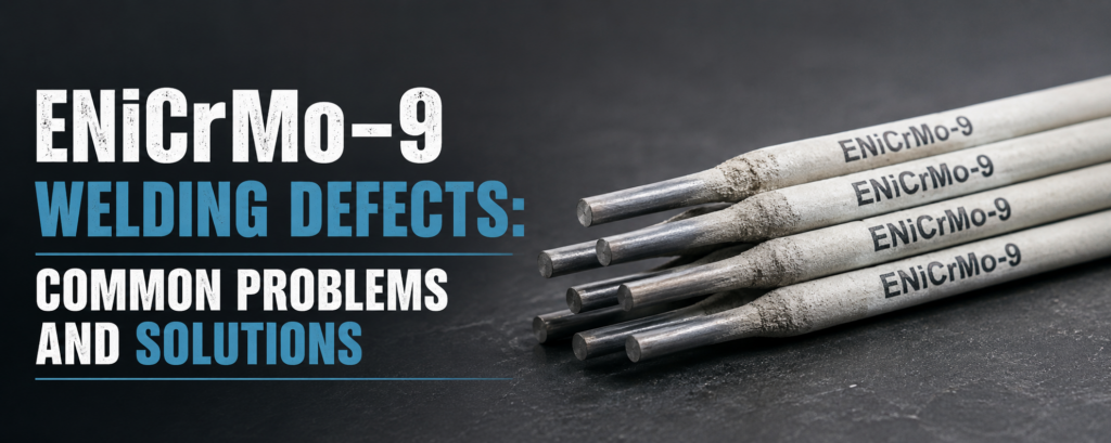
ENiCrMo-9 Welding Defects: Common Problems and Solutions
ENiCrMo-9 is a nickel-chromium-molybdenum covered electrode used for shielded metal arc welding of compatible corrosion-resistant nickel alloys. It is commonly associated with UNS N06985 base material and may also be considered for approved dissimilar-metal joints, weld overlays, and clad-steel fabrication.
Although ENiCrMo-9 electrodes can produce corrosion-resistant weld deposits, successful welding depends heavily on surface cleanliness, electrode condition, joint preparation, arc length, heat input, bead placement, and interpass cleaning.
Nickel-alloy weld pools behave differently from ordinary carbon-steel weld pools. The molten metal is often less fluid and may not spread automatically into the joint sidewalls. As a result, poor technique can lead to porosity, slag inclusions, incomplete fusion, undercut, cracking, irregular bead shape, and other discontinuities.
This guide explains the most common ENiCrMo-9 welding defects, why they occur, how to prevent them, and how to repair defective weld areas correctly.
What Is an ENiCrMo-9 Electrode?
ENiCrMo-9 is a covered nickel-alloy electrode intended for the shielded metal arc welding process, also called SMAW or stick welding.
Its deposited weld metal contains nickel, chromium, molybdenum, iron, and controlled quantities of additional alloying elements. This chemistry is designed to provide compatibility with specific corrosion-resistant nickel alloys while maintaining useful mechanical properties and resistance to aggressive chemical environments.
Typical applications include:
Chemical processing equipment
Process piping
Pressure vessels
Heat exchangers
Acid-handling systems
Pollution-control equipment
Corrosion-resistant weld overlays
Repair of compatible nickel-alloy components
Approved nickel-alloy-to-steel joints
The electrode classification alone does not guarantee a successful weld. The complete welding procedure must consider the base material, service environment, design temperature, joint thickness, welding position, dilution, inspection requirements, and applicable fabrication code.
Why ENiCrMo-9 Welding Defects Occur
Most ENiCrMo-9 welding defects are caused by one or more of the following conditions:
Moisture in the electrode coating
Oil, grease, paint, dirt, or oxide on the joint
Incorrect amperage
Excessive arc length
Incorrect polarity
Poor joint geometry
Inadequate root opening
Excessive travel speed
Poor sidewall arc placement
Incomplete slag removal
Excessive weaving
Improper crater termination
High restraint
Excessive heat accumulation
Contamination from carbon-steel tools
Defects are rarely solved by changing only one parameter. Reliable results usually require a systematic review of the electrode condition, welding machine, joint preparation, welder technique, and inspection findings.
1. Porosity in ENiCrMo-9 Weld Metal
Porosity appears as rounded or elongated gas cavities in the weld metal. It may be visible at the surface or remain hidden inside the completed joint.
Porosity can occur as:
Scattered pores
Cluster porosity
Surface-breaking pores
Wormhole porosity
Crater pores
Linear porosity near the root
Common Causes of Porosity
The most frequent causes include:
Damp ENiCrMo-9 electrodes
Improper electrode storage
Oil or grease on the joint
Moisture on cold base material
Paint, marking compounds, or cutting residue
Excessive arc length
Excessive amperage
Damaged electrode coating
Unstable arc conditions
Welding over contaminated tack welds
Moisture in the electrode coating can release gases into the molten weld pool. If the weld metal solidifies before these gases escape, cavities remain in the deposit.
A long arc can also reduce the effectiveness of the protective atmosphere created by the electrode coating, increasing exposure to air.
ENiCrMo-9 How to Prevent Porosity
Store opened electrodes in a heated holding oven.
Follow the specified reconditioning procedure for moisture-exposed electrodes.
Discard electrodes with cracked or damaged coatings.
Remove oil, grease, moisture, paint, and marking residue.
Keep the arc as short as practical.
Use the correct polarity and current range.
Do not weld on visibly damp material.
Grind contaminated tack welds to clean metal.
Avoid striking the arc outside the prepared joint.
How to Repair Porosity
Do not simply cover visible pores with another weld pass.
Remove the affected area by grinding or machining until sound metal is reached. Blend the excavation smoothly, clean it thoroughly, and verify that no additional pores remain. The repair may then be rewelded using dry electrodes and corrected parameters.
For critical welds, penetrant or radiographic examination may be required after repair.
2. Slag Inclusions
Slag inclusions occur when flux residue becomes trapped between weld passes or inside the weld metal.
They are especially common in multipass SMAW joints with poor bead shape, narrow grooves, deep undercut, or insufficient interpass cleaning.
ENiCrMo-9 Common Causes of Slag Inclusions
Incomplete slag removal
Low welding current
Excessively convex beads
Wide weave beads
Poor electrode angle
Narrow groove angle
Insufficient root opening
Fast or irregular travel
Welding over undercut
Poor overlap between adjacent beads
Failure to grind starts and stops
Nickel-alloy weld metal does not flow as freely as many steel weld metals. If the bead is placed incorrectly, narrow valleys can form along the sidewalls or between adjacent passes. Slag may remain trapped in these areas even after wire brushing.
How to Prevent Slag Inclusions
Remove all slag after every pass.
Use a dedicated stainless-steel wire brush.
Grind stubborn slag from bead valleys and stop areas.
Maintain a short arc.
Use sufficient current for stable arc force.
Avoid excessively wide weaving.
Provide adequate access through correct joint design.
Place beads so that each pass overlaps smoothly.
Correct undercut before depositing the next layer.
Grind irregular bead profiles when necessary.
ENiCrMo-9 How to Repair Slag Inclusions
Locate the full length and depth of the inclusion before repair. Remove the affected weld metal completely rather than opening only the visible surface.
After excavation:
Inspect the cavity.
Remove all remaining slag and oxide.
Blend sharp corners.
Clean the area to bright metal.
Reweld with controlled bead placement.
Perform the required final examination.
3. Incomplete Fusion
Incomplete fusion occurs when the deposited weld metal does not fuse completely with the base material or a previous weld layer.
It may occur at:
Groove sidewalls
The root face
Between weld passes
Tack-weld locations
Starts and stops
Areas containing surface oxide
Incomplete fusion is a serious defect because it creates a sharp internal discontinuity that can reduce joint strength and provide a crevice where corrosion may begin.
ENiCrMo-9 Common Causes of Incomplete Fusion
Insufficient welding current
Excessive travel speed
Poor electrode angle
Incorrect arc placement
Narrow joint preparation
Large root face
Oxide or slag on the previous pass
Excessive bead size
Poor access to the sidewall
Failure to remove defective tack welds
How to Prevent Incomplete Fusion
Use a joint angle wide enough for electrode access.
Maintain the specified root opening.
Direct the arc toward both joint sidewalls.
Use a controlled travel speed.
Select the correct current for the electrode diameter.
Remove oxide and slag before each pass.
Avoid depositing oversized beads.
Use smaller electrodes in restricted joint areas.
Grind tack-weld ends before incorporating them into the joint.
Because nickel-alloy weld metal is relatively sluggish, the welder must deliberately place the molten metal rather than expecting it to wash automatically across the joint.
ENiCrMo-9 How to Repair Incomplete Fusion
Remove the affected region completely by grinding or machining. The excavation must extend beyond the entire unfused area.
After removal, confirm that:
Both sidewalls are accessible.
No slag or oxide remains.
The cavity has smooth transitions.
The root or backing area is sound.
The revised joint geometry permits complete fusion.
Reweld using a shorter arc, corrected angle, slower travel speed, and better sidewall control.
4. Incomplete Root Penetration
Incomplete penetration occurs when the weld does not extend completely through the joint root as required by the design.
This defect is often associated with butt joints, pipe roots, and thick-section groove welds.
Common Causes
Root opening too small
Root face too large
Misalignment
Insufficient current
Electrode diameter too large
Excessive travel speed
Poor access to the root
Incorrect electrode position
Inadequate back-gouging
ENiCrMo-9 Prevention Methods
Verify the root opening before welding.
Maintain consistent fit-up with suitable tack welds.
Use the electrode diameter specified by the WPS.
Remove excessive root-face thickness.
Control alignment and hi-low.
Use the correct current and travel speed.
Back-gouge the second side to clean metal when required.
Inspect the root pass before filling the joint.
In corrosive service, incomplete penetration can create a crevice that traps process fluids. Therefore, full penetration may be important for both mechanical integrity and corrosion resistance.
5. Weld Cracking
Cracking is one of the most serious ENiCrMo-9 welding defects. A crack can develop during solidification, cooling, repair welding, or later service.
Cracks may appear as:
Centerline cracks
Crater cracks
Toe cracks
Root cracks
Transverse cracks
Longitudinal cracks
Heat-affected-zone cracks
ENiCrMo-9 Common Causes of Cracking
Contamination by sulfur, phosphorus, lead, or other low-melting materials
Oil, grease, paint, or marking compounds
High joint restraint
Concave bead shape
Unfilled craters
Excessive heat input
Improper repair geometry
Arc strikes outside the joint
Welding over an existing crack
Poor tack-weld preparation
Nickel-alloy welds are particularly sensitive to certain contaminants. Even small amounts of undesirable material can concentrate near solidifying grain boundaries and increase cracking risk.
How to Prevent Weld Cracking
Clean the joint thoroughly before welding.
Use tools reserved for nickel-alloy fabrication.
Avoid sulfur-containing markers and lubricants.
Design the joint to reduce unnecessary restraint.
Deposit slightly convex rather than deeply concave beads.
Fill the crater before breaking the arc.
Grind tack-weld ends and arc stops.
Control bead size and heat input.
Do not weld over visible cracks.
Use a balanced welding sequence for restrained assemblies.
ENiCrMo-9 How to Repair Cracks
A crack must be removed completely. Welding directly over it will not produce a reliable repair.
The recommended repair sequence is:
Determine the crack length.
Mark both ends of the crack.
Grind beyond the visible crack tips.
Remove the full crack depth.
Perform surface examination.
Confirm complete crack removal.
Clean the excavation.
Reweld using the approved repair procedure.
Repeat the required inspection.
6. Crater Cracks and Crater Pipes
A crater crack forms when the arc is stopped abruptly and the end of the weld bead is not filled properly.
As the small crater solidifies, shrinkage stresses can create a central crack or a slag-filled cavity.
Common Causes
Abrupt arc termination
Failure to fill the crater
Excessively concave bead ending
High welding current
Poor restart preparation
Excessive joint restraint
Prevention Methods
Before extinguishing the arc:
Pause briefly to fill the crater.
Use a slight back-step motion.
Move the arc toward a joint sidewall after filling.
Avoid leaving a deep depression.
Grind every stop before restarting a critical weld.
Restart slightly behind the prepared end of the previous bead.
7. Undercut
Undercut is a groove melted into the base material beside the weld toe that is not filled with weld metal.
It reduces the effective thickness of the joint and can create a stress concentration or corrosion site.
ENiCrMo-9 Common Causes
Excessive amperage
Long arc length
Excessive travel speed
Incorrect electrode angle
Wide weaving
Failure to pause at the sidewall
Poor control in vertical or overhead positions
How to Prevent Undercut
Reduce amperage when necessary.
Maintain a short arc.
Slow the travel speed.
Use controlled manipulation.
Pause briefly at each sidewall.
Avoid wide weave beads.
Use a smaller electrode for positional welding.
Maintain a consistent drag or work angle.
Minor undercut may be blended by grinding when permitted. Deeper undercut generally requires weld repair according to the acceptance criteria.
8. Overlap and Cold Lap
Overlap occurs when weld metal rolls onto the base surface without fully fusing to it.
The bead may appear smooth externally, but the unfused edge creates a sharp discontinuity.
Common Causes
Welding current too low
Travel speed too slow
Electrode angle directed away from the fusion line
Excessive deposition in one pass
Poor manipulation of the sluggish weld pool
Oversized electrode for the joint
Prevention Methods
Increase current within the approved range.
Improve arc placement at the toe.
Use smaller controlled beads.
Increase travel speed slightly.
Avoid allowing the weld pool to run ahead of the arc.
Use a suitable electrode diameter.
Overlap should be removed by grinding and rewelded with proper fusion.
9. Excessive Weld Reinforcement
Excessive reinforcement creates an unnecessarily high, narrow, or convex weld profile.
Some convexity can be beneficial in nickel-alloy welding, but an excessively raised bead can increase stress concentration and make slag removal difficult.
Common Causes
Low amperage
Slow travel speed
Electrode diameter too large
Narrow joint angle
Excessive weld metal deposition
Poor bead sequencing
Prevention Methods
Use the correct current range.
Maintain a steady travel speed.
Select an appropriate electrode size.
Use multiple smaller beads instead of one oversized pass.
Improve the joint angle.
Blend adjacent beads smoothly.
10. Excessive Spatter
Under correct ENiCrMo-9 welding conditions, excessive spatter should not occur.
Common Causes
Excessive arc length
Excessive amperage
Incorrect polarity
Moisture in the electrode coating
Unstable power supply
Magnetic arc blow
Damaged electrode coating
Solutions
Shorten the arc.
Reduce current.
Confirm the required polarity.
Use dry, undamaged electrodes.
Check cable and ground connections.
Adjust the ground location when arc blow occurs.
Use shorter electrodes near the end of difficult joints when permitted.
Spatter should be removed after welding because attached particles can damage the protective surface condition and create small crevice-like areas.
11. Arc Strikes
An arc strike is an accidental arc mark outside the intended weld area.
Arc strikes may contain localized cracks, surface damage, or altered corrosion behavior.
Prevention Methods
Strike the arc inside the prepared joint.
Use run-on tabs when appropriate.
Protect surrounding surfaces.
Maintain stable electrode control.
Position the work lead to reduce arc instability.
Any accidental arc strike should be lightly ground to sound metal and examined according to the project requirements.
12. Oxide Inclusions and Heat Tint
Oxides may form on the weld surface, adjacent base material, or previous weld layers.
If high-melting oxide is not removed before the next pass, it can contribute to incomplete fusion or oxide inclusions.
Common Causes
Incomplete interpass cleaning
Excessive heat input
Welding over discolored surfaces
Contaminated grinding tools
Failure to remove cutting oxides
Prevention Methods
Grind the joint to bright metal before welding.
Remove visible oxide between passes.
Use clean, iron-free abrasive tools.
Control heat input and interpass temperature.
Clean both sides of corrosion-service welds where required.
Postweld surfaces should be left clean and free from slag, spatter, embedded iron, and loose oxide.
13. Distortion
Nickel-alloy components can distort when heat input and welding sequence are not controlled.
Common Causes
Excessive weld size
Long continuous beads
Poor tack-weld sequence
Unbalanced welding
Inadequate fixturing
Excessive interpass temperature
Uneven joint gaps
ENiCrMo-9 How to Reduce Distortion
Use the minimum weld size required by the design.
Apply balanced welding sequences.
Use properly spaced tack welds.
Weld from the center outward where suitable.
Alternate welding sides.
Allow the joint to cool between passes.
Use fixtures that do not create excessive restraint.
Maintain uniform fit-up.
Correct ENiCrMo-9 Welding Technique
A consistent technique helps prevent several defects at the same time.
ENiCrMo-9 Joint Preparation
The groove must provide adequate access for the electrode and arc. Narrow grooves can make sidewall fusion and slag removal difficult.
Before welding:
Remove scale and oxide.
Remove oil and grease.
Grind cutting surfaces to clean metal.
Correct alignment problems.
Confirm root opening and groove angle.
Prepare tack welds for incorporation into the joint.
ENiCrMo-9 Electrode Storage
Keep unopened electrodes in their original sealed packaging. Once opened, store them under the conditions stated in the electrode instructions.
Do not invent a rebaking temperature. Coating formulations differ, and an unsuitable heating cycle may damage the electrode.
Current and Polarity
Use the current and polarity specified by the qualified WPS and electrode instructions. Direct current electrode positive is common for nickel-alloy covered electrodes, but the exact requirement must be verified.
Excessive current can overheat the coating and reduce arc control. Insufficient current may cause unstable operation, excessive convexity, slag entrapment, and poor fusion.
Arc Length
Maintain a short arc. This improves:
Weld-pool control
Slag control
Bead shape
Arc stability
Fusion consistency
Protection from atmospheric contamination
ENiCrMo-9 Bead Technique
Controlled stringer beads or narrow weave beads are generally preferred. Avoid uncontrolled wide weaving.
The welder should actively direct the arc toward the fusion boundaries and maintain a bead profile that permits complete slag removal.
ENiCrMo-9 Interpass Cleaning
After every pass:
Remove the slag.
Brush the surface.
Grind irregular areas.
Inspect the bead toes.
Remove oxide and visible defects.
Confirm that the next pass has a clean fusion surface.
Inspection Methods for ENiCrMo-9 Welds
Inspection requirements depend on the joint design, service conditions, construction standard, and acceptance criteria.
ENiCrMo-9 Visual Inspection
Visual examination can identify:
Surface porosity
Cracks
Undercut
Overlap
Excessive reinforcement
Incomplete fill
Arc strikes
Spatter
Poor crater termination
Remaining slag
Liquid Penetrant Examination
Liquid penetrant testing is commonly used for detecting surface-breaking cracks and pores in nonmagnetic nickel alloys.
The weld must be cleaned thoroughly before testing. All penetrant materials must also be removed after inspection, especially before repair welding.
ENiCrMo-9 Radiographic Examination
Radiography may reveal:
Internal porosity
Slag inclusions
Incomplete penetration
Certain fusion defects
Internal cracks
ENiCrMo-9 Ultrasonic Examination
Ultrasonic testing may be used when the joint geometry, thickness, procedure, and acceptance standard make it suitable. Nickel-alloy weld-metal structure can affect sound transmission, so the examination technique must be properly qualified.
ENiCrMo-9 Weld Repair Procedure
A controlled repair procedure should include:
Review the inspection report.
Confirm the defect type and location.
Mark the complete repair area.
Remove the defect by grinding or machining.
Avoid overheating the surrounding metal.
Blend the excavation smoothly.
Examine the cavity for complete defect removal.
Clean the repair area.
Use dry ENiCrMo-9 electrodes.
Reweld with controlled heat input.
Clean each repair layer.
Perform final inspection.
Repeated repairs in the same location should trigger a technical review. The original defect may be related to poor joint design, excessive restraint, contamination, or an unsuitable welding sequence rather than welder technique alone.
ENiCrMo-9 Conclusion
The most common ENiCrMo-9 welding defects include porosity, slag inclusions, incomplete fusion, incomplete penetration, cracking, undercut, overlap, excessive reinforcement, spatter, arc strikes, oxide inclusions, and distortion.
Most of these problems can be prevented through disciplined control of five essential factors: cleanliness, electrode storage, joint preparation, short-arc welding technique, and complete interpass cleaning.
ENiCrMo-9 weld metal requires deliberate placement and careful slag control. Welders should not rely on the molten pool to flow automatically into poorly prepared sidewalls or narrow joint areas.
For reliable corrosion-resistant welds, every production and repair weld should follow a qualified welding procedure, use correctly stored electrodes, and receive the inspection required for its intended service.
Technical classifications and nickel-alloy SMAW defect-control principles were verified against recognized welding specifications and fabrication guidance.