

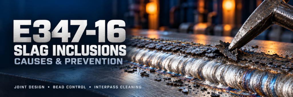
Slag Inclusions in E347-16 Welds: Why They Occur
Slag inclusions in E347-16 welds develop when nonmetallic material becomes trapped inside the weld instead of separating from the molten metal or being removed between passes. The problem often involves a combination of restricted joint access, unfavorable bead shape, incomplete cleaning and poor control of the weld pool.
E347-16 is a niobium-stabilized stainless steel electrode commonly used for welding suitable 321 and 347 stainless steels. Its coating produces a protective slag layer during shielded metal arc welding, or SMAW. That layer is necessary for the process, but it must remain under control during welding and be removed before depositing subsequent passes.
Understanding where slag becomes trapped is the first step toward preventing recurring defects.
What Are Slag Inclusions in E347-16 Welds?
A slag inclusion is solid nonmetallic material embedded in the deposited weld metal or along a fusion boundary. In E347-16 welding, this material can originate from the electrode coating and reactions associated with welding.
Inclusions may appear as isolated particles, elongated indications or discontinuous lines between weld passes. Some become visible after surface cleaning or grinding, while others remain completely internal.
Their significance depends on size, shape, location and the applicable acceptance criteria. An inclusion is a weld imperfection; whether it constitutes a rejectable defect must be determined against the governing specification.
Slag Inclusions vs. Porosity and Lack of Fusion
These imperfections require different corrective actions.
| Imperfection | What It Is | Main Diagnostic Question |
|---|---|---|
| Slag inclusion | Nonmetallic solid trapped in the weld | Where did slag remain or become enclosed? |
| Porosity | Gas cavities in solidified weld metal | What introduced gas or prevented its escape? |
| Lack of fusion | Failure to fuse adjacent metal surfaces | Did the arc properly melt the sidewall or previous bead? |
Slag inclusions and lack of fusion can occur together. Simply increasing current or cleaning more aggressively may fail if the underlying problem is inaccessible joint geometry.
Why Slag Inclusions Occur in E347-16 Welds
1. Incomplete Cleaning Between Passes
Residual slag from an earlier pass can be covered by the next deposit. The most difficult areas are often weld toes, narrow grooves, craters and valleys between adjacent beads.
A bead that appears clean across its center may still retain slag along its edges. Inspect the entire surface that the next pass will cover.
Where chipping and brushing cannot remove trapped material, controlled grinding may be necessary.
2. Bead Profiles Create Slag Pockets
Highly convex beads can leave deep valleys beside the deposit. When the next bead bridges across these valleys, slag may become enclosed.
Poorly arranged adjacent beads can create the same problem even when each individual bead looks acceptable.
The aim is a profile that allows cleaning and subsequent fusion. Avoid evaluating bead appearance separately from the shape of the remaining groove.
3. Joint Access Is Too Restricted
A narrow groove, unsuitable root configuration or oversized electrode can prevent the welder from directing the arc toward the required surfaces.
Restricted access also makes cleaning more difficult. The result may be repeated inclusions near sidewalls or between passes.
Check whether the electrode can reach the joint without an excessively long arc or an awkward angle. Groove design and electrode diameter should work together.
4. Current and Travel Speed Are Poorly Matched
Current that is too low for the electrode and position may produce poor wetting and an unfavorable bead profile. Excessive travel speed can leave insufficient time for proper sidewall fusion and slag separation.
Conversely, excessive current or very slow travel can create a large, difficult-to-control pool.
The objective is balanced pool control, rather than maximum current or minimum travel speed. Use the selected electrode’s recommended range and the qualified welding procedure.
5. Electrode Angle Allows Slag to Interfere with Fusion
An unsuitable work angle can direct heat away from a sidewall. An unsuitable travel angle can contribute to slag moving into the area where fusion should occur.
The correct technique depends on joint type, position and electrode behavior. Observe the boundary between molten metal and slag, rather than relying only on the appearance of the completed bead.
6. Excessive Weaving Reduces Control
A wide weave can make it difficult to control the pool and consistently fuse both sides of the joint. It may also create uneven bead edges that retain slag.
Where permitted by the procedure, narrower beads can improve access and cleaning. They still require suitable overlap and careful placement.
7. Starts and Stops Are Poorly Prepared
Restart locations can retain slag in an irregular crater or steep bead end. Depositing directly over that area may trap material beneath the new pass.
Clean the restart thoroughly and prepare its profile when necessary. The new deposit must fuse into sound metal.
A Practical Troubleshooting Guide
The location of an indication helps identify what to investigate first.
| Recurring Location | Possible Contributors | First Checks |
|---|---|---|
| Along a groove sidewall | Restricted access, poor work angle, inadequate fusion | Groove width, electrode size and arc direction |
| Between adjacent beads | Deep valleys, poor overlap, retained slag | Bead profile and placement sequence |
| At starts and stops | Contaminated crater or unsuitable restart profile | Cleaning and restart preparation |
| Near the root | Difficult access, unsuitable root geometry | Fit-up and root-pass technique |
| Throughout several layers | Inconsistent cleaning or pool control | Cleaning practice, parameters and electrode condition |
These patterns guide the investigation but do not replace inspection or examination of representative sections.
How to Prevent Slag Inclusions in E347-16 Welding
Prepare a Joint That Can Be Welded and Cleaned
Confirm groove dimensions, alignment and root configuration before welding. Provide sufficient access for the selected electrode and cleaning tools.
Remove oil, dirt and other contamination. Use tools suitable for stainless steel to avoid introducing embedded carbon-steel contamination.
Follow a Qualified Welding Procedure
Specify electrode diameter, current type, polarity, current range, welding position and relevant thermal controls.
E347-16 products commonly support AC or DCEP, but settings should follow the specific product instructions. Do not assume that every electrode diameter or formulation behaves identically.
Inspect Every Pass Before Covering It
After removing slag, examine weld toes, bead intersections and restart areas. Correct pockets and unfavorable profiles before proceeding.
A later pass should not be used as an assumed remedy for visible retained slag.
Plan Bead Placement
Choose a sequence that leaves accessible surfaces and avoids deep channels between deposits. Adjust placement as the groove fills.
For multipass welds, consistent bead geometry often matters as much as cleaning effort.
Maintain Electrode Condition
Protect electrodes from moisture, contamination and coating damage. Follow the manufacturer’s storage and re-drying instructions.
Do not automatically apply baking temperatures intended for a different electrode classification. Moisture-related problems can also include porosity and unstable operation, so electrode condition should be assessed separately from confirmed slag entrapment.
How Are Slag Inclusions Detected?
Visual inspection identifies exposed imperfections and conditions likely to trap slag. It cannot establish that the weld interior is free of inclusions.
Radiographic testing can reveal suitable internal indications, depending on their size, orientation and the inspection technique.
Ultrasonic testing may also be applicable. However, austenitic stainless steel weld structures can complicate sound propagation and interpretation, making an appropriate procedure and qualified personnel essential.
During procedure development, macrosections can help show the relationship between inclusions, bead placement and fusion boundaries. They reveal only the sections examined.
Repairing Slag Inclusions in E347-16 Welds
When an inclusion exceeds the applicable acceptance criteria, remove the affected material using an approved repair method.
The repair cavity should expose sound metal and provide adequate access for welding and cleaning. Reweld using the applicable repair procedure, then perform the required inspection.
Before repairing, identify the cause. Repeating the same joint access, bead shape or cleaning problem can reproduce the inclusion.
Frequently Asked Questions
Does E347-16 naturally produce slag?
Yes. Slag formation is part of the coated-electrode welding process. A surface slag layer is expected; slag trapped inside the weld is an imperfection.
E347-16 Will higher current eliminate slag inclusions?
Not necessarily. Higher current may improve wetting in some circumstances, but it will not correct retained slag, poor joint access or unsuitable bead placement. Excessive current can reduce pool control.
E347-16 Can slag inclusions occur in a single-pass weld?
Yes. Slag can become trapped during deposition, particularly when it interferes with fusion or cannot escape before solidification.
E347-16 Does niobium cause slag inclusions?
Niobium stabilization does not, by itself, explain trapped slag. Investigation should focus on deposition conditions, joint geometry, cleaning and electrode performance.
E347-16 Conclusion
Slag inclusions in E347-16 welds are best investigated through their location and the conditions that allowed material to become trapped. Effective prevention combines accessible joint design, suitable parameters, controlled bead placement and thorough inspection between passes.
When inclusions recur, examine the complete welding sequence. Correcting the underlying cause provides a more reliable result than changing one parameter in isolation.