

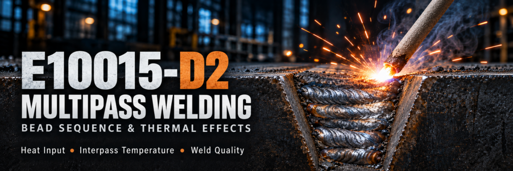
E10015-D2 Multipass Welding: Bead Sequence and Thermal Effects
In E10015-D2 multipass welding, bead sequence determines more than how a groove is filled. It controls where heat enters the joint, how earlier deposits are reheated, and how weld shrinkage develops. Together with heat input and interpass temperature, bead placement influences fusion, microstructure, toughness, hardness, and cracking risk.
The central challenge is consistency. A weld can have an acceptable surface appearance while its internal thermal history differs significantly from the conditions used during procedure qualification.
Understanding these relationships helps fabricators develop repeatable welding practices and evaluate the completed joint more effectively.
What Is E10015-D2?
E10015-D2 is a low-alloy steel covered electrode classification for shielded metal arc welding, or SMAW. It uses a low-hydrogen sodium covering and belongs to the manganese-molybdenum alloy group.
Its designation identifies the following characteristics:
| Designation | Meaning |
|---|---|
| E | Covered welding electrode |
| 100 | Minimum tensile strength class of 100,000 psi under classification test conditions |
| 1 | All-position classification, subject to applicable size and usability requirements |
| 5 | Low-hydrogen sodium covering operated with direct current electrode positive |
| D2 | Manganese-molybdenum alloy composition group |
The strength designation describes classification performance under specified testing conditions. Actual joint properties also depend on base-metal dilution, welding parameters, cooling conditions, and any subsequent heat treatment.
Why Multipass Welding Changes the Weld Metal
Every pass creates a new thermal cycle.
The first bead solidifies and cools. Later beads partially remelt or reheat portions of that deposit. Depending on their distance from the new arc, earlier regions may experience complete transformation, partial transformation, or lower-temperature tempering.
As a result, a multipass weld contains several thermal histories within the same joint.
As-Deposited Regions
These regions retain much of their original solidification structure and cooling history. Portions of the final cap often remain in this condition because no subsequent layer reheats them.
E10015-D2 Reheated Regions
Earlier weld metal can be heated above transformation temperatures and develop a different microstructure as it cools again. Some thermal cycles refine particular regions, while others produce less favorable local structures.
Tempered Regions
Lower-temperature reheating can temper susceptible microstructures and change hardness. However, the effect depends on both temperature and exposure time.
Additional passes do not automatically improve toughness. The outcome depends on the combination of alloy composition, peak temperature, cooling rate, and repeated reheating.
Planning the Root, Fill, and Cap Sequence
A practical E10015-D2 bead sequence should support sound fusion, accessible cleaning, controlled temperature, and an acceptable final profile.
Root Pass: Establish Penetration and Fusion
The root pass creates the foundation for the remaining weld.
Joint preparation, root opening, electrode access, and welding technique must allow the required penetration and fusion. An excessively convex or irregular root can make subsequent bead placement more difficult.
Root regions may also experience greater base-metal dilution than later deposits. This can alter local chemistry and transformation behavior.
Clean and inspect the root before covering it. Unacceptable defects require correction under the approved procedure.
Fill Passes: Maintain a Manageable Layer Profile
Fill passes should build the groove without creating deep valleys or narrow slag pockets.
When several beads are needed in one layer, place them so that adjacent deposits fuse properly and remain accessible for cleaning. Electrode angle, bead overlap, and travel technique must suit the groove and welding position.
Avoid treating a single left-to-right or center-out sequence as universally suitable. The appropriate arrangement depends on joint geometry, access, and the qualified welding technique.
Cap Passes: Control Reinforcement and Weld Toes
Cap passes establish the final surface profile.
Excessive reinforcement adds deposited metal without necessarily improving joint performance. Poor toe blending, undercut, or abrupt profile changes may create unacceptable conditions.
Because the final layer receives less subsequent reheating, its properties can differ from those of the underlying layers. Cap bead size and heat input therefore deserve the same control as root and fill passes.
E10015-D2 Bead Placement Across the Groove and Along the Joint
Two different sequences should be considered.
Across the groove, bead placement determines layer shape, overlap, sidewall access, and local reheating.
Along the joint, welding order influences heat distribution, shrinkage, and distortion.
For suitable joints, balanced welding on opposite sides or specified skip and back-step sequences may help control deformation. Their effectiveness depends on restraint, component dimensions, and joint configuration.
These methods also change the time between passes and introduce additional starts and stops. Any distortion-control sequence must remain compatible with preheat, interpass temperature, and restart requirements.
Heat Input and Cooling Rate
Heat input affects weld-pool size and the rate at which the weld and surrounding material cool.
For steady-current welding, arc energy can be estimated using:
Arc energy (kJ/mm) = Voltage × Current × 60 ÷ [1,000 × Travel speed (mm/min)]
Where required by the governing calculation method, a thermal-efficiency factor is applied to obtain heat input.
This distinction matters when comparing procedure records. Values calculated using different conventions should not be treated as directly equivalent.
When Heat Input Is Too Low
Rapid cooling may produce harder microstructures in susceptible materials. Low heat input can also contribute to inadequate fusion when combined with unsuitable current, travel speed, or electrode manipulation.
When Heat Input Is Too High
Excessive thermal exposure can change weld-metal transformation behavior and enlarge affected regions. Depending on the material, it may reduce strength or impact toughness.
The objective is a qualified operating range. Neither the lowest nor the highest possible heat input provides the best result for every E10015-D2 joint.
Interpass Temperature: Managing Heat Accumulation
Interpass temperature is measured before depositing the next pass. It reflects the thermal condition from which the next welding cycle begins.
A thick joint may cool rapidly into the surrounding material. A short joint or localized repair can accumulate heat quickly during repeated welding.
Minimum Interpass Temperature
The specified minimum helps control cooling and supports hydrogen diffusion. Allowing a susceptible joint to cool below this limit may increase cracking risk.
After an interruption, restore the required temperature before restarting.
Maximum Interpass Temperature
The maximum limits excessive heat accumulation and helps maintain the conditions associated with qualified mechanical properties.
If the joint exceeds this limit, follow the approved cooling or sequencing practice before continuing. Do not use uncontrolled water cooling to accelerate production.
Measure temperature at the prescribed location and time. A hot weld surface does not prove that the entire required region meets the minimum temperature.
Stringer Beads or Weaving?
Stringer beads can provide controlled bead dimensions and straightforward placement when several deposits are needed across a layer.
Weaving can cover a wider area, but weave width and sidewall dwell affect local heating, bead shape, and slag behavior.
A broad weave may increase thermal exposure. However, stringer beads do not automatically mean lower overall heat input: their current, travel speed, and number also matter.
Use the technique permitted by the welding procedure specification, or WPS. Evaluate its ability to achieve fusion and required properties rather than selecting it solely for appearance.
Interpass Cleaning and Start-Stop Control
Slag removal is essential in E10015-D2 multipass welding.
Slag can remain at bead toes, sidewalls, and uneven layer transitions. Depositing another pass over these areas can trap inclusions.
Before each pass:
Remove slag and loose surface contamination.
Examine bead toes and sidewall transitions.
Prepare starts and stops where required.
Correct unacceptable discontinuities.
Confirm that the joint is within the permitted temperature range.
Staggering starts and stops may help avoid concentrating restart locations, where permitted. It cannot compensate for poor crater filling or inadequate restart fusion.
E10015-D2 Hydrogen Control Throughout the Weld
Low-hydrogen electrodes still require controlled storage and handling.
Moisture pickup, contaminated joints, and unsuitable thermal conditions can increase hydrogen-assisted cracking risk. The relevant interaction involves hydrogen, susceptible microstructure, and tensile stress.
Repeated reheating may encourage hydrogen to escape, but it does not guarantee that the weld is free from cracking.
Larger deposits can increase the distance hydrogen must diffuse. Increasing bead size or heat input should therefore not replace proper electrode conditioning, temperature control, and procedure compliance.
For planned interruptions, define how the joint will be maintained, cooled, inspected, and reheated before work resumes.
E10015-D2 Multipass Reheating Versus Post-Weld Heat Treatment
Multipass reheating is localized and uneven. Post-weld heat treatment, or PWHT, applies a controlled temperature-time cycle to the specified region or component.
The two processes are not interchangeable.
If PWHT is required, verify mechanical properties in the intended heat-treated condition. Repeated or extended heat-treatment cycles may change performance and should be evaluated when relevant to fabrication or repair.
Hydrogen-release postheating is also distinct from stress-relief PWHT. Each treatment needs its own defined purpose and procedure.
E10015-D2 How to Verify a Multipass Welding Procedure
Verification should connect the actual welding technique to the required joint performance.
| Check | Purpose |
|---|---|
| Welding parameter records | Confirm current, voltage, travel speed, and calculated energy |
| Temperature records | Demonstrate preheat and interpass control |
| Macro examination | Evaluate penetration, fusion, and bead arrangement |
| Nondestructive testing | Detect relevant surface or internal discontinuities |
| Tensile testing | Assess strength under the specified test conditions |
| Impact testing | Evaluate toughness at the required temperature and location |
| Hardness testing | Identify local hardness variations |
Record bead placement and sequencing during qualification. These details make production instructions more useful than a parameter range alone.
Building a Repeatable E10015-D2 Multipass Process
Reliable E10015-D2 multipass welding combines a clear bead plan with controlled thermal conditions. Root preparation, fill-layer geometry, cap placement, cleaning, and restart technique all contribute to the result.
Use the qualified procedure to coordinate heat input, preheat, interpass temperature, and any post-weld treatment. Verify the completed joint using the tests required for its application.