

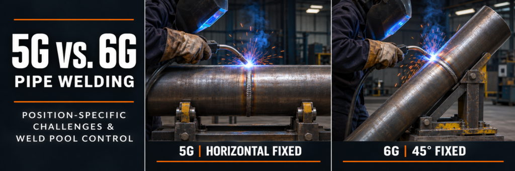
5G vs. 6G Pipe Welding: Position-Specific Challenges and Weld Pool Control
The main difference between 5G vs. 6G pipe welding is the orientation of the fixed pipe. In 5G, the pipe axis is horizontal. In 6G, the pipe axis is inclined at approximately 45 degrees. Neither position allows the pipe to rotate during welding.
5G vs. 6G pipe welding That difference changes how the welder approaches the joint and manages molten metal. Both positions require adjustments around the circumference, but 6G adds an inclined groove that makes body positioning, sidewall fusion, and weld pool balance more demanding.
Understanding these challenges helps welders recognize problems early and produce more consistent root, fill, and cap passes.
5G vs. 6G Pipe Welding: Key Differences
| Feature | 5G pipe welding | 6G pipe welding |
|---|---|---|
| Pipe axis | Horizontal | Inclined approximately 45 degrees |
| Pipe rotation | Fixed | Fixed |
| Welding conditions | Transitions through overhead, vertical, and flat regions | Combined positional changes around an inclined joint |
| Main control challenge | Adjusting to gravity around the circumference | Managing gravity, groove inclination, and changing access together |
| Body positioning | Requires planned movement around the pipe | Often requires more frequent changes in stance and hand support |
| Typical learning focus | Consistent transitions between welding regions | Maintaining control through less symmetrical working conditions |
The position designation describes the setup. It does not specify the welding process, filler metal, current, or direction of progression. Those choices belong in the welding procedure specification, or WPS.
Why Weld Pool Control Changes Around a Fixed Pipe
On a rotating pipe, the joint can remain in a favorable working position. On a fixed pipe, the welder must follow the joint as its orientation relative to gravity changes.
A technique that produces a stable bead near the top may create an oversized or sagging pool underneath. Likewise, a comfortable electrode angle on one side may become difficult to maintain after moving around the joint.
Effective weld pool control requires attention to three visible features:
The leading edge: Is the arc reaching the joint where fusion is needed?
The sidewalls: Are both edges melting and tying into the deposited metal?
The trailing pool: Is the metal solidifying into a controlled profile or accumulating unevenly?
Watching these features provides more useful feedback than following a fixed hand rhythm alone.
Position-Specific Challenges in 5G Pipe Welding
Overhead Region: Keeping the Pool Manageable
At the underside of a horizontal fixed pipe, gravity pulls molten metal away from the joint. An oversized pool becomes difficult to support and can produce an irregular bead.
The objective is a compact, controllable pool with sufficient fusion. Simply lowering current is not always the answer: an excessively cold arc can reduce fusion while making the bead appear easier to manage.
Maintain the arc length appropriate to the process and consumable. Coordinate travel speed and deposition so metal does not build up faster than it can solidify.
Vertical Regions: Balancing Fusion and Metal Movement
5G vs. 6G welding Along the sides of the pipe, gravity encourages molten metal to move downward. The challenge depends partly on whether the approved procedure uses uphill or downhill progression.
For uphill welding, excessive dwell can enlarge the pool and allow it to sag. Moving too quickly can leave inadequate sidewall fusion.
For downhill welding, travel speed, arc placement, and consumable suitability become especially important. A downhill technique should not be substituted for uphill progression without confirming that the procedure permits it.
Top Region: Avoiding Excessive Accumulation
Near the top, the pool has more support, but that does not eliminate control problems. Slowing excessively can produce an overly wide bead or excessive reinforcement.
As access becomes easier, maintain deliberate travel and deposition rather than allowing the pool to grow. The goal is a consistent joint profile through the transition.
Why 6G Pipe Welding Is More Demanding
The Inclined Groove Encourages Uneven Metal Distribution
In 6G welding, the joint itself is inclined. Depending on the local position, molten metal can favor the lower side of the groove, leaving unequal bead buildup or poor tie-in at the opposite edge.
The welder must observe both sidewalls independently. A centered-looking electrode does not guarantee balanced fusion.
Adjust the working angle as required by the local joint orientation and approved technique. Avoid using one fixed angle around the entire circumference.
Access Changes Before the Bead Is Finished
A common problem is reaching the limit of a comfortable stance while continuing to weld. As the arm extends, arc length and travel angle can drift.
Plan the welding sequence before striking the arc. Check visibility, cable clearance, and hand support throughout the intended section.
5G vs. 6G pipe welding Where necessary, use a planned stop and controlled restart rather than continuing after visibility and movement become unreliable.
One Side May Feel Easier Than the Other
The inclined setup can make one side more accessible to the welder’s dominant hand. The opposite side may require a different stance or support arrangement.
Practice both sides under comparable conditions. A successful bead on the easier side does not demonstrate consistent control around the full joint.
Root Pass Control in 5G and 6G Welding
The root pass establishes the initial connection through the joint. Its consistency depends on preparation as well as welding technique.
Before welding, check:
Root opening and root face against the WPS.
Internal alignment and allowable mismatch.
Cleanliness of the groove and adjacent surfaces.
Tack weld condition and permitted preparation.
Backing or internal shielding requirements, where applicable.
An uneven root opening changes the local welding conditions. Trying to compensate entirely through hand movement can create inconsistent penetration.
Monitor the Root Opening as You Progress
For open-root techniques that use a keyhole, observe whether the opening remains controlled. A rapidly enlarging keyhole can indicate that the local combination of heat, gap, and travel is becoming difficult to manage. A closing keyhole may indicate insufficient melting at the root.
Keyhole behavior is process-dependent. Not every root technique uses a visible keyhole, so the assessment must match the procedure.
Give Restarts the Same Attention as Continuous Welding
Restarts and tack tie-ins deserve close inspection. Depositing metal over a poorly prepared stop can leave an unfused area beneath an acceptable-looking surface.5G vs. 6G welding
Prepare and clean the stop using permitted methods, then establish fusion into the previous deposit before advancing. Follow the specified restart technique rather than relying on extra filler metal to cover the transition.
5G vs. 6G welding Fill and Cap Passes: Building a Consistent Profile
Fill passes create the surface that supports the cap. Uneven fill makes the final layer harder to control, particularly where an inclined groove encourages metal to collect on one side.5G vs. 6G welding.
Use bead placement that maintains access to the remaining groove faces. Clean between passes and inspect for visible imperfections before covering them.
Narrow stringer beads can help limit pool size where permitted. A weave may be appropriate for some procedures, but excessive width or prolonged pauses can increase heat accumulation.5G vs. 6G welding
For the cap, concentrate on smooth toe transitions and the required profile. A uniform surface is useful evidence of control, but appearance alone cannot confirm internal weld quality.
5G vs. 6G welding Common Weld Pool Problems and What to Check
| Observed problem | Possible contributing factors | What to review |
|---|---|---|
| Pool sagging | Excessive pool size, slow travel, unsuitable angle | Deposition, travel speed, and local working angle |
| Unequal sidewall tie-in | Inclined groove, poor visibility, arc misdirection | Both fusion edges and electrode orientation |
| Incomplete root penetration | Fit-up variation, insufficient melting, excessive travel speed | Root geometry and procedure parameters |
| Slag inclusions | Incomplete cleaning, poor bead placement, slag moving ahead | Interpass cleaning and access to fusion boundaries |
| Undercut | Unsuitable angle, excessive current, incorrect travel or manipulation | Toe behavior and permitted parameter range |
| Irregular cap | Uneven fill, inconsistent deposition, unstable movement | Fill profile, stance, and bead sequence |
These symptoms can have several causes. Diagnose the local condition before changing a setting.
5G vs. 6G welding Choosing Parameters for Fixed-Position Pipe Welding
There is no universal amperage setting for either position. Suitable parameters depend on the process, material, wall thickness, joint preparation, consumable, and pass sequence.5G vs. 6G welding
Use the approved WPS to establish the operating range. During practice, change one permitted variable at a time and compare the results. This makes it easier to identify whether an improvement came from travel speed, angle, deposition, or another adjustment.
Also monitor preheat and interpass temperature where specified. The joint’s thermal condition can change as welding progresses, even when machine settings remain constant.5G vs. 6G welding
5G vs. 6G welding Improving Consistency in Both Positions
Reliable fixed-position pipe welding starts with consistent fit-up and a workable movement plan. In 5G, focus on controlling transitions between the underside, sides, and top. In 6G, add careful attention to the inclined groove and unequal access.
5G vs. 6G pipe welding Practice should reproduce the actual joint conditions, including difficult sections and restarts. Assess each pass before continuing, and use the inspection methods required by the job to verify the finished weld.5G vs. 6G welding