

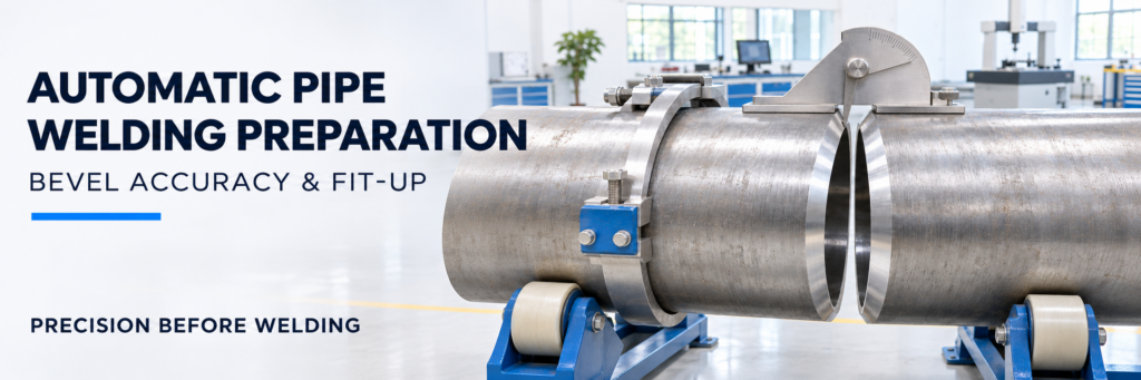
Automatic Pipe Welding Preparation determines whether a programmed welding cycle can produce consistent results around a pipe joint. Bevel angle, root face thickness, root opening, and internal alignment all influence the conditions encountered by the welding arc. When these dimensions vary beyond the demonstrated process window, even repeatable equipment can produce inconsistent penetration, poor fusion, or an unacceptable root profile.
Automatic Pipe Welding Preparation: Why Bevel Accuracy Matters
An automatic welding system follows defined settings for current, voltage, travel speed, wire feeding, and torch movement. These settings work within a particular range of joint geometries.
If the groove changes significantly around the circumference, the same welding program encounters different thermal and deposition requirements. A section with a thicker root face may need more energy to achieve penetration, while a thinner section may become vulnerable to excessive penetration.
Accurate machining therefore does more than improve the appearance of the pipe end. It helps establish repeatable conditions for the root pass and subsequent layers.
Automatic Pipe Welding Preparation: Bevel Angle and Groove Profile
Bevel angle affects access to the root, sidewall heating, groove volume, and the space available for torch movement.
A groove that is too narrow for the selected equipment may restrict wire placement or prevent effective heating of both sidewalls. An unnecessarily wide groove increases the volume that must be filled and may require changes to bead placement.
Drawings should distinguish between the bevel angle on one pipe end and the total included angle of the assembled joint. Confusing these measurements can produce a substantially different groove.
For compound bevels, inspection should also cover the transition between angles. Checking only the opening at the pipe surface can miss errors deeper in the joint.
The correct profile depends on the welding process, pipe material, wall thickness, and qualified procedure. A conventional manual-welding bevel should not automatically be adopted for an automated system.
Root Face Thickness and Uniformity
The root face, sometimes called the land, strongly influences root-pass behavior.
An excessively thick land can resist complete penetration under the selected settings. An excessively thin land may melt too quickly, especially where the root opening is larger than intended.
Uniformity around the circumference is as important as the nominal dimension. Pipe ovality, wall-thickness variation, and the machining reference can affect the finished land.
Inspection should confirm both the specified thickness and its circumferential consistency. Where internal geometry varies, the machining method must account for that variation rather than assuming the outside surface provides a sufficient reference.
Automatic Pipe Welding Preparation: Root Gap and Internal Alignment
Establishing the Correct Root Opening
The root gap must match the selected root-pass technique. Some procedures require a controlled opening; others are developed for close-fitting or nominally zero-gap joints.
A larger gap is not automatically better for penetration. Depending on the process, it can increase the risk of excessive penetration, an irregular root profile, or burn-through. A smaller gap can also prevent satisfactory root formation when the procedure depends on an open root.
Measure the assembled joint around its circumference. A satisfactory reading at the top does not establish acceptable conditions at the sides or bottom.
Recheck the opening after final clamping and tacking, where applicable. The joint must remain within the required range when welding starts.
Controlling Internal Misalignment
Internal misalignment, commonly called hi-lo, occurs when the adjoining internal surfaces do not line up.
Matching the outside diameters does not necessarily align the bore. Differences in wall thickness and pipe shape can leave an internal step even when the external joint appears satisfactory.
This offset can make root fusion and profile control more difficult. It can also create an unfavorable geometric discontinuity in the completed joint.
Use suitable alignment equipment and measurement methods to assess the internal condition. Pipe rotation or matching may improve fit-up, but any corrective machining must preserve the required wall thickness and approved joint design.
Clamping arrangements should provide stable alignment without relying on uncontrolled force to conceal an unsuitable fit.
Automatic Pipe Welding Preparation: Setting Practical Tolerances
Why Universal Numerical Limits Are Misleading
There is no single bevel angle, root gap, or hi-lo limit suitable for every automatic welding application.
Required tolerances depend on:
Welding process and root-pass technique.
Pipe diameter, material, and wall thickness.
Joint profile and backing arrangement.
Torch access and positioning accuracy.
Tracking and adaptive-control capabilities.
Applicable construction requirements and project specifications.
The welding procedure and supporting qualification establish the basis for production. Representative trials should then demonstrate that the equipment can handle the intended fit-up range.
A permitted construction tolerance may be wider than the range an individual welding system can handle reliably. Production controls must satisfy both the applicable requirements and the demonstrated capability of the process.
Evaluating Combined Variations
Dimensions should not be assessed only in isolation.
A slightly thicker land, a slightly smaller gap, and local misalignment may each appear manageable separately. When they occur together at one location, they can create a much more demanding root condition.
Procedure development should consider realistic combinations of variation. Testing only an ideal joint provides limited evidence of production robustness.
Adaptive control can help accommodate measured changes, but its adjustment range must be demonstrated. A tracking system that follows the joint centerline does not necessarily identify or correct every root-geometry problem.
Automatic Pipe Welding Preparation: Inspection Before Welding
A practical inspection plan should connect each measurement to a documented acceptance limit and a defined response when that limit is exceeded.
| Inspection item | What to verify | Why it matters |
|---|---|---|
| Bevel angle | Correct angle and circumferential consistency | Maintains intended access and groove volume |
| Compound profile | Correct transition geometry and depth | Supports the planned root and fill sequence |
| Root face | Thickness and uniformity | Helps stabilize root penetration |
| Root opening | Gap around the assembled circumference | Maintains the intended root-pass conditions |
| Internal alignment | Local bore offset | Supports root fusion and profile control |
| Pipe-end condition | Squareness, damage, and burrs | Prevents irregular assembly and local interference |
| Joint cleanliness | Removal of oil, moisture, scale, and machining residue | Reduces contamination-related discontinuities |
| Clamping and tacking | Stable geometry before welding | Limits movement during the welding cycle |
Use calibrated tools suited to the feature being measured. Record local out-of-tolerance conditions rather than averaging them into an apparently acceptable result.
If the joint fails inspection, correct the fit-up, remachine the end where permitted, or refer the condition for an approved disposition. Unplanned parameter changes should not become a substitute for acceptable preparation.
Building Repeatable Production Quality
Reliable automatic welding begins with a joint the equipment has been shown to weld.
Accurate bevel machining, consistent root geometry, clean surfaces, and stable alignment reduce the variation that the welding program must accommodate. Together with a qualified procedure and effective inspection, these controls support more predictable root quality and fewer avoidable repairs.