

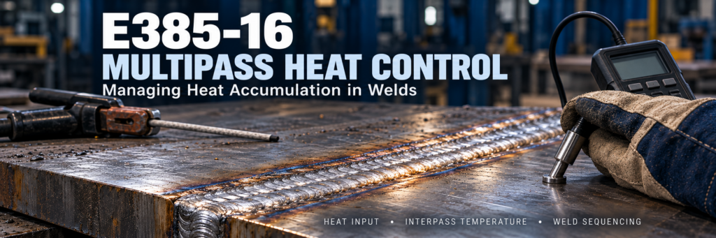
Managing Heat Accumulation in E385-16 Multipass Welds
Heat accumulation can turn an otherwise stable E385-16 welding procedure into a source of inconsistent bead shape, distortion, and weld defects. During multipass welding, each new bead introduces heat into a joint that may still be warm from earlier passes. If heat enters faster than the component can release it, the starting temperature rises progressively.
For E385-16 electrodes used to weld 904L stainless steel and similar materials, managing this cumulative thermal exposure is an essential part of procedure control. A reliable approach combines controlled heat input, measured interpass temperature, suitable bead geometry, and a planned welding sequence.
Why Heat Accumulates During E385-16 Multipass Welding
Multipass welds experience repeated heating and cooling. A root pass heats the surrounding material, while subsequent fill and cap passes reheat both the joint and previously deposited weld metal.
Austenitic stainless steels conduct heat less efficiently than carbon steels, so heat tends to remain concentrated near the weld. Their relatively high thermal expansion also makes dimensional control important.
Heat accumulation becomes especially noticeable when:
- Several passes are deposited continuously in one small area.
- Short joints leave little time for cooling between passes.
- Thin sections have limited capacity to absorb heat.
- High current is combined with slow travel speed.
- Wide weaving increases local arc dwell time.
- Multiple welders work close together on the same component.
Joint thickness alone does not determine the risk. A thick assembly can retain substantial heat during prolonged welding, while a thin component can reach an excessive temperature after only a few passes.
Why Thermal Control Matters for E385-16 Welds
E385-16 typically deposits a highly alloyed, fully austenitic weld metal. Its thermal behavior and solidification characteristics require attention throughout the welding operation.
Solidification Cracking
Fully austenitic weld metal can be susceptible to solidification cracking. Crack formation depends on several interacting factors, including weld chemistry, segregation, joint restraint, dilution, and bead geometry.
Excessive thermal exposure can contribute to unfavorable welding conditions, but controlling temperature alone does not eliminate cracking. Clean joints, suitable parameters, and careful crater filling remain necessary.
Changes in Weld Pool Behavior
As the joint becomes hotter, the weld pool may become larger and harder to control even when the machine settings remain unchanged. Beads can become wider, and maintaining a consistent profile may become more difficult.
This is why settings that produce a satisfactory root pass may require reassessment during later passes, within the limits of the approved procedure.
Distortion and Dimensional Variation
Uneven heating and contraction can cause angular distortion, shrinkage, and loss of alignment. Continuous welding on one side of an assembly can make these effects more pronounced.
Corrosion Performance
Repeated thermal cycles can influence weld and heat-affected-zone microstructures. Surface oxidation, contamination, and weld segregation also affect corrosion performance.
However, an elevated interpass temperature does not automatically prove that a weld has lost corrosion resistance. The effect depends on the actual thermal history, material chemistry, surface condition, and service environment.
Heat Input and Interpass Temperature: Two Different Controls
Heat input describes the energy applied per unit length of weld. Interpass temperature describes the temperature of the joint before the next pass begins.
Both need control.
A weld can remain within its heat-input limit while exceeding its interpass-temperature limit if passes are deposited too quickly. Conversely, a cool joint can still receive excessive energy from a slow, high-current pass.
For conventional welding calculations, arc energy can be expressed as:
\[ E=\frac{V \times I \times 60}{1000 \times S} \]
Where:
- \(E\) = arc energy in kJ/mm
- \(V\) = arc voltage in volts
- \(I\) = welding current in amperes
- \(S\) = travel speed in mm/min
When the applicable calculation method includes process efficiency, heat input is:
\[ Q=\eta E \]
Where \(\eta\) is the specified thermal efficiency factor.
For example, 25 V, 100 A, and a travel speed of 150 mm/min give an arc energy of 1.0 kJ/mm before applying any efficiency factor. This illustrates the calculation; it is not a recommended E385-16 operating setting.
Use the calculation method required by the governing specification and welding procedure.
Establish the Interpass Temperature Limit Before Welding
The E385-16 classification does not establish one universal interpass-temperature limit for every application.
The welding procedure specification should define the limit using the base material requirements, electrode guidance, procedure qualification, and service conditions. Requirements can differ between products and projects.
An effective temperature-control procedure identifies:
- The maximum permitted interpass temperature.
- The measurement location relative to the weld.
- The instrument and measurement method.
- When measurements must be taken.
- The action required when the limit is exceeded.
Measure before depositing the next pass. Checking only after welding does not demonstrate that the starting temperature met the procedure.
Measure Temperature Consistently
Suitable measurement tools may include contact thermometers, thermocouples, temperature-indicating products, and appropriately configured infrared instruments.
Consistency matters as much as instrument selection. Readings taken at different distances from the weld may represent very different temperatures.
Infrared measurements require particular care on reflective stainless steel surfaces. Emissivity settings, surface finish, and viewing conditions can affect the result. Use a validated method rather than relying on an unverified handheld reading.
For critical work, record temperature alongside the pass number and welding parameters. This helps identify when the joint begins to retain more heat than expected.
Use Bead Geometry to Manage Local Heating
Stringer beads often provide better control of local thermal exposure than broad weaving. They allow the welder to build the joint with relatively narrow deposits and limited side-to-side movement.
Wide weaving can increase dwell time, particularly when the arc pauses at the groove edges. It may also make heat input less consistent along the bead.
Where permitted by the procedure:
- Keep bead width controlled.
- Maintain steady travel speed.
- Avoid unnecessary pauses.
- Use enough energy to achieve fusion.
- Remove slag before depositing the next bead.
Narrow beads are not automatically a guarantee of low total heat input. They may require more passes, so temperature must still be monitored throughout the joint.
Match Electrode Diameter to the Pass
Larger electrodes generally operate at higher currents and can increase deposition rate. Whether they increase energy per unit length also depends on voltage and travel speed.
Use an electrode diameter suitable for the groove, welding position, and required access. Smaller electrodes may improve control in root passes or confined areas, but excessively low current can produce poor fusion and unstable operation.
The objective is a stable arc and sound fusion within the qualified thermal limits.
Plan the Welding Sequence Around Heat Distribution
A practical welding sequence gives heated regions time to cool while useful work continues elsewhere.
Alternate Between Suitable Locations
On assemblies with several joints, moving between separated weld locations can reduce repeated heating of one area. Before returning to a joint, verify its temperature.
Balance Welding Across the Assembly
Where geometry and the procedure allow, distribute welding across opposing sides or sections. This can help control uneven contraction and distortion.
Coordinate Multiple Welders
Two welders working near the same joint can raise the local temperature faster than either expects. Their sequence and temperature checks should be coordinated.
Review Short Joints Carefully
On a short joint, an electrode change may not provide enough cooling time. Deliberate pauses may be necessary even when production is progressing normally.
E385-16 Allow Controlled Cooling Between Passes
When the temperature exceeds the procedure limit, stop welding at that location and allow the joint to cool.
Do not substitute a fixed waiting time for a temperature measurement. Cooling time changes with component mass, joint geometry, ambient conditions, and previous passes.
Avoid improvised cooling methods. Water spraying, immersion, or unapproved forced cooling can introduce contamination and alter the thermal cycle. Use cooling arrangements only when they are included in the approved procedure.
E385-16 Keep Cleaning Separate from Temperature Verification
Slag removal and inspection naturally create time between passes, but they do not confirm that the joint has cooled sufficiently.
Use tools dedicated to stainless steel to limit contamination. Remove slag completely, inspect accessible areas, and verify the temperature before restarting.
Heat tint should also be addressed during the specified post-weld surface treatment. Its appearance alone is not a reliable measurement of interpass temperature.
E385-16 Troubleshooting Heat Accumulation
| Observation | Possible contributor | Practical response |
|---|---|---|
| Temperature rises with each pass | Insufficient cooling time | Pause or move to another approved location |
| Beads become progressively wider | Higher starting temperature or slower travel | Check temperature and actual travel speed |
| Weld pool becomes difficult to control | Hot joint or unsuitable parameters | Cool the joint and review procedure settings |
| Distortion increases | Unbalanced heat distribution | Review sequence, fit-up, and restraint |
| Crater cracks appear | Crater filling, restraint, or solidification conditions | Review stopping technique and investigate the cause |
| Fusion deteriorates after reducing current | Energy reduced too far | Restore qualified parameters and control temperature through cooling |
A defect should trigger an investigation rather than an automatic reduction in current. Lowering current without considering fusion can replace one problem with another.
E385-16 Conclusion
Managing heat accumulation in E385-16 multipass welds requires control of both the energy applied during each pass and the temperature before the next pass begins. Consistent measurement, suitable electrode selection, controlled beads, and a balanced welding sequence help maintain stable conditions throughout the joint.
Build these controls into the welding procedure and production records so that weld quality remains consistent from the root pass to the final cap.