

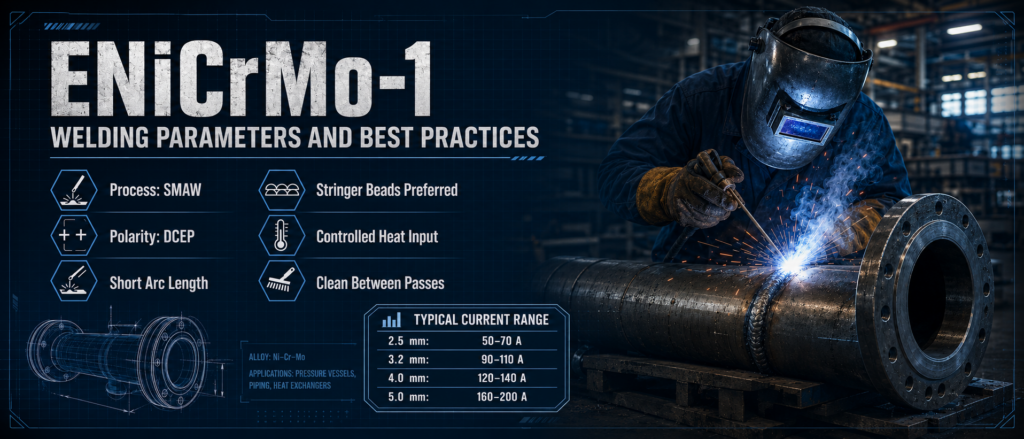
ENiCrMo-1 Welding Parameters and Best Practices
ENiCrMo-1 is a nickel-chromium-molybdenum covered electrode designed for shielded metal arc welding. It is commonly selected for joining compatible nickel alloys, welding nickel-alloy-clad steel, applying corrosion-resistant overlays, and making certain dissimilar-metal joints.
Achieving a sound ENiCrMo-1 weld requires more than selecting the correct electrode. Current, polarity, arc length, heat input, joint cleanliness, bead placement, and interpass temperature all affect weld quality. Poor control of these variables can lead to porosity, slag inclusions, incomplete fusion, excessive dilution, or cracking.
This guide explains typical ENiCrMo-1 welding parameters and practical techniques for producing clean, consistent, and corrosion-resistant weld deposits.
What Is an ENiCrMo-1 Welding Electrode?
ENiCrMo-1 is classified as a nickel-chromium-molybdenum electrode for the shielded metal arc welding process, also known as SMAW or stick welding. The deposited weld metal is nickel based and contains controlled amounts of chromium, molybdenum, iron, copper, and other alloying elements.
This alloy system is designed to provide a combination of:
Resistance to aggressive chemical environments
Good weld-metal strength
Useful elevated-temperature performance
Resistance to weld cracking
Compatibility with selected nickel-alloy base materials
Reliable performance in corrosion-resistant overlays
ENiCrMo-1 should not be confused with ERNiCrMo-1. ENiCrMo-1 is a flux-covered stick electrode used for SMAW, while ERNiCrMo-1 is a bare filler metal intended for processes such as gas tungsten arc welding or gas metal arc welding.
Typical ENiCrMo-1 Welding Parameters
The correct amperage depends on electrode diameter, welding position, joint design, base-metal thickness, and the specific electrode formulation. The following values are practical starting ranges rather than universal settings.
| Electrode Diameter | Typical Current Range | Recommended Use |
|---|---|---|
| 2.5 mm | 50–70 A | Thin sections, roots, and controlled repair work |
| 3.2 mm | 90–110 A | General fabrication and smaller groove welds |
| 4.0 mm | 120–140 A | Flat-position filling and medium-thickness joints |
| 5.0 mm | 160–200 A | High-deposition flat-position welding |
Always confirm the final amperage range with the electrode data sheet and the approved welding procedure specification.
Begin near the lower-middle part of the recommended range. Increase the current only when the arc is unstable, fusion is insufficient, or the bead is excessively convex. Reduce the current when the puddle becomes difficult to control, the coating overheats, or the weld bead becomes too wide and fluid.
Recommended Polarity for ENiCrMo-1
ENiCrMo-1 electrodes are generally welded using:
Direct Current Electrode Positive, or DCEP
DCEP is also called reverse polarity or DC positive. The electrode holder is connected to the positive terminal, while the workpiece is connected to the negative terminal.
Using the recommended polarity supports stable arc characteristics, proper electrode melting, and reliable slag behavior. Incorrect polarity may cause:
An unstable arc
Excessive spatter
Poor bead shape
Incomplete fusion
Irregular slag coverage
Reduced electrode performance
Alternating current should not be used unless it is specifically permitted by the electrode documentation and the qualified welding procedure.
Welding Position
The flat position is generally preferred for ENiCrMo-1 because nickel-alloy weld pools can remain fluid and require careful control. Horizontal welding may also be possible when supported by the selected electrode and welding procedure.
Smaller-diameter electrodes provide better control for positional welding. Electrodes larger than approximately 3.2 mm are normally better suited to flat or horizontal work because the larger weld pool is more difficult to manage vertically or overhead.
For vertical welding:
Use a smaller electrode
Reduce the amperage
Weld vertical-up unless the procedure specifies otherwise
Use narrow stringer beads
Keep the arc short
Pause briefly at the sidewalls when necessary
Avoid excessive weaving
Positional welding should only be performed when it is allowed by the electrode classification, product instructions, and qualified procedure.
Joint Preparation for ENiCrMo-1 Welding
Nickel-alloy weld metal does not penetrate as deeply as some carbon-steel weld deposits under similar conditions. The joint must therefore provide adequate access to the root and sidewalls.
A suitable joint design may require:
A wider groove angle
A controlled root opening
A consistent root face
Smooth transitions
Adequate access for slag removal
Sufficient space for electrode manipulation
Do not assume that a carbon-steel joint design will automatically be suitable for a nickel-alloy weld.
Before production begins, confirm that the joint geometry matches the welding procedure. Irregular root openings and narrow groove angles can trap slag and increase the risk of incomplete fusion.
Surface Cleaning and Contamination Control
Cleanliness is one of the most important ENiCrMo-1 welding best practices. Nickel-alloy welds are sensitive to contamination from oil, grease, moisture, paint, cutting fluids, sulfur-bearing compounds, and foreign metals.
Before welding:
Remove oil and grease with an approved residue-free cleaner.
Remove oxide, scale, paint, and dirt from the joint area.
Clean both sides of the joint where accessible.
Use dedicated brushes and grinding tools.
Keep the electrode and joint surfaces dry.
Prevent contact with copper, lead, zinc, and other low-melting contaminants.
Use a clean stainless-steel wire brush that is reserved for nickel-alloy work. Tools previously used on carbon steel can transfer iron particles and compromise the corrosion performance of the finished weld.
Cleaning should extend beyond the visible weld groove. Contamination close to the joint can be drawn into the molten pool during welding.
Preheat and Interpass Temperature
Nickel alloys normally do not require high preheat temperatures. In many cases, the purpose of warming the joint is simply to remove condensation or moisture rather than to alter the metallurgical cooling rate.
Before welding, the joint should be:
Dry
Free from condensation
Above the minimum temperature required by the procedure
Protected from rain, frost, and cold drafts
Excessive preheat should be avoided because nickel alloys have relatively low thermal conductivity. Heat can accumulate quickly around the weld zone, increasing the risk of distortion, excessive dilution, and undesirable weld-metal structure.
As a general practice, keep the interpass temperature below approximately 150°C unless the approved procedure specifies another limit. Use temperature crayons, contact thermometers, or other suitable measuring equipment rather than estimating the temperature by touch.
Allow the joint to cool between passes when necessary.
Arc Length and Electrode Angle
A short, controlled arc is essential when welding with ENiCrMo-1.
An excessively long arc can increase:
Atmospheric contamination
Porosity
Spatter
Arc wandering
Undercut
Irregular bead appearance
Maintain an arc length approximately equal to or slightly shorter than the electrode core diameter. Avoid whipping the electrode far away from the weld pool.
For flat welding, use a slight drag angle, generally around 5 to 15 degrees in the direction of travel. The exact angle should be adjusted to maintain clear visibility of the leading edge of the weld pool and to prevent slag from moving ahead of the arc.
Do not use an extreme drag angle. Excessive electrode inclination can trap slag and reduce sidewall fusion.
Use Stringer Beads Instead of Wide Weaves
Stringer beads are generally preferred for ENiCrMo-1 welding. They help control heat input, reduce puddle size, and improve access for interpass cleaning.
Wide weaving should be avoided because it can:
Increase total heat input
Produce an oversized weld pool
Reduce travel speed
Increase distortion
Trap slag along the sidewalls
Create inconsistent penetration
Increase dilution into the base metal
When weaving is necessary, keep the movement narrow and controlled. The bead width should remain within the limits established by the welding procedure.
Do not hold the arc in the center of the joint for too long. When sidewall fusion requires additional attention, use a brief controlled pause at each side rather than a slow, wide oscillation.
ENiCrMo-1 Travel Speed and Heat Input
Travel speed should be fast enough to prevent excessive heat buildup but slow enough to achieve complete fusion.
A travel speed that is too slow may cause:
Excessively wide beads
High heat input
Increased dilution
Distortion
Difficult slag control
Overheating of the electrode coating
A travel speed that is too fast may cause:
Incomplete fusion
Undercut
Narrow, highly convex beads
Poor tie-in at the weld toes
Slag entrapment
Watch the leading edge of the weld pool rather than focusing only on the arc. The arc should melt both sidewalls while the molten metal fills the joint evenly behind it.
Nickel-alloy weld pools can appear less fluid than carbon-steel weld pools. Do not respond automatically by increasing the amperage. First verify the arc length, electrode angle, joint access, and travel speed.
ENiCrMo-1 Starting and Stopping the Weld
Arc starts and stops require careful attention because crater defects and slag entrapment often develop in these areas.
At the start of a bead:
Strike the arc on clean metal
Establish a stable pool before moving forward
Avoid striking the arc outside the weld zone
Remelt the end of the previous bead when restarting
At the end of a bead:
Reduce travel speed slightly
Fill the crater
Avoid leaving a deep depression
Do not break the arc abruptly
Grind defective stops before continuing
For critical joints, stagger the starts and stops of adjacent passes. Avoid placing multiple arc stops at the same location through the thickness of the weld.
ENiCrMo-1 Slag Removal Between Passes
Complete slag removal is essential. Nickel-alloy electrode slag can remain tightly attached in narrow grooves, at weld toes, or around irregular restarts.
After every pass:
Allow the slag to cool sufficiently.
Remove the main slag layer.
Brush the entire bead surface.
Inspect both toes and restart areas.
Grind out trapped slag, undercut, or irregular bead shapes.
Clean the surface again before depositing the next pass.
Do not weld over visible slag. Even a small remaining particle can form a linear inclusion when covered by the next bead.
A smooth, slightly convex bead with clean sidewall tie-in provides a better foundation for the following pass.
ENiCrMo-1 Electrode Storage and Handling
Covered electrodes must remain dry. Moisture in the coating can contribute to porosity, arc instability, excessive spatter, and irregular slag behavior.
Recommended handling practices include:
Store unopened packages in a dry indoor area
Keep electrodes away from floors and exterior walls
Open only the quantity needed for the job
Return unused electrodes to controlled storage promptly
Use heated storage when required by the supplier
Do not use electrodes with cracked, damaged, or flaking coatings
Recondition damp electrodes only according to the specified instructions
Do not apply a generic rebaking temperature without checking the electrode documentation. Excessive heating can damage the coating and change welding performance.
ENiCrMo-1 How to Reduce Dilution
Dilution is especially important when ENiCrMo-1 is used for cladding, surfacing, or dissimilar-metal welding. Excessive mixing with the base metal can reduce the intended corrosion resistance of the deposited layer.
To limit dilution:
Use the lowest current that still provides complete fusion
Maintain a short arc
Avoid excessive penetration
Use narrow stringer beads
Control electrode angle
Use multiple layers when required
Avoid unnecessary weaving
Follow the specified bead sequence
The first overlay layer usually experiences the greatest dilution. Additional layers may be required to achieve the target weld-metal chemistry at the finished surface.
Final acceptance should be based on the applicable procedure, chemical requirements, inspection plan, and service conditions.
Common ENiCrMo-1 Welding Problems
Porosity
Possible causes:
Moisture in the electrode coating
Oil, grease, paint, or dirt
Excessive arc length
Condensation on the joint
Damaged electrode coating
Corrective actions:
Use dry electrodes
Clean the joint thoroughly
Shorten the arc
Remove moisture before welding
Reject damaged electrodes
ENiCrMo-1 Slag Inclusions
Possible causes:
Incomplete cleaning between passes
Narrow groove angle
Excessive electrode angle
Low amperage
Wide weaving
Corrective actions:
Remove all slag between passes
Improve joint access
Use a more neutral electrode angle
Adjust current within the approved range
Deposit narrow stringer beads
Incomplete Fusion
Possible causes:
Current is too low
Travel speed is too fast
Groove is too narrow
Arc is directed away from the sidewall
The previous bead has an irregular profile
Corrective actions:
Increase current slightly
Reduce travel speed
Improve joint preparation
Direct the arc at the leading edge of the pool
Grind irregular areas before continuing
Undercut
Possible causes:
Excessive current
Long arc
Fast travel speed
Incorrect electrode angle
Excessive weaving
Corrective actions:
Reduce current
Shorten the arc
Adjust travel speed
Correct the electrode angle
Use smaller stringer beads
Arc Instability
Possible causes:
Incorrect polarity
Poor electrical connections
Damp electrodes
Excessive arc length
Current outside the recommended range
Corrective actions:
Confirm DCEP polarity
Check the work clamp and cable connections
Replace damp electrodes
Maintain a short arc
Reset the amperage
ENiCrMo-1 Welding Best-Practice Checklist
Before welding:
Verify the base-metal grade
Confirm the filler-metal classification
Review the approved welding procedure
Check electrode condition and storage
Clean the joint and surrounding surfaces
Confirm joint dimensions
Check polarity
Select the correct electrode diameter
Set the initial amperage
Confirm the required preheat and interpass limits
During welding:
Maintain a short arc
Use narrow stringer beads
Control heat input
Watch sidewall fusion
Keep a steady travel speed
Fill all craters
Measure interpass temperature
Remove slag after every pass
Inspect each layer before continuing
After welding:
Remove all slag and spatter
Inspect the weld profile
Check for undercut and incomplete fill
Perform the required visual and nondestructive examinations
Protect the finished surface from contamination
Record the welding variables when required
ENiCrMo-1 Conclusion
Successful ENiCrMo-1 welding depends on disciplined control of every stage of the operation. Correct polarity and amperage are important, but joint cleanliness, heat control, arc length, bead placement, slag removal, and electrode storage are equally critical.
For most applications, use DCEP, maintain a short arc, deposit narrow stringer beads, keep the interpass temperature controlled, and clean thoroughly between passes. Treat the amperage values in this guide as starting points and finalize all parameters through an approved welding procedure.
When these ENiCrMo-1 welding best practices are followed, fabricators can achieve more consistent fusion, lower defect rates, controlled dilution, and reliable corrosion-resistant weld deposits.