

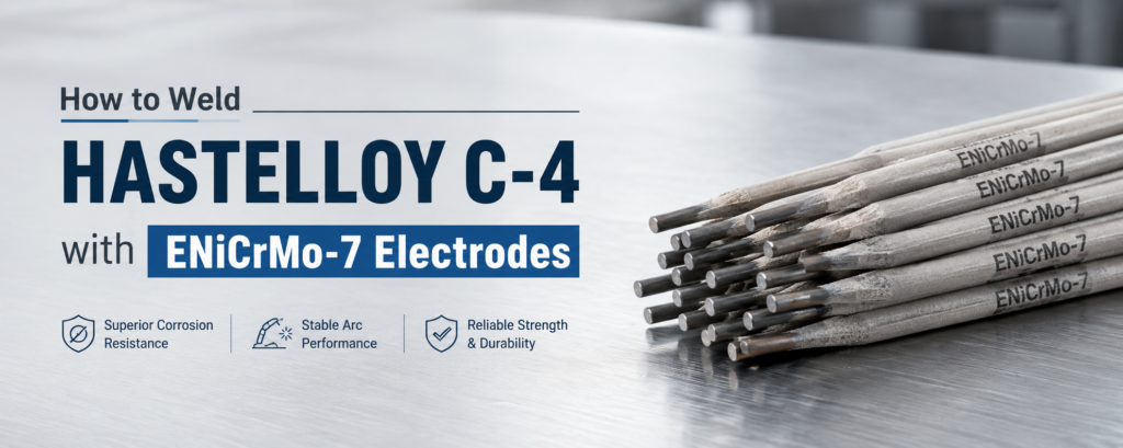
How to Weld Hastelloy C-4 with ENiCrMo-7 Electrodes
Welding Hastelloy C-4 requires more than selecting a nickel-alloy electrode and striking an arc. Although the alloy has excellent weldability and strong resistance to heat-affected-zone sensitization, the finished joint can only deliver reliable corrosion performance when the joint is clean, the heat is controlled, and every layer is completely free of slag and oxide contamination.ENiCrMo-7
ENiCrMo-7 electrodes are matching nickel-chromium-molybdenum covered electrodes commonly selected for shielded metal arc welding of Hastelloy C-4. Their weld deposit is designed to provide chemical compatibility with the base material while maintaining corrosion resistance in aggressive chemical environments.
This guide explains how to weld Hastelloy C-4 with ENiCrMo-7 electrodes, from joint preparation and parameter selection to interpass cleaning, defect prevention, and final inspection.
What Is Hastelloy C-4?
Hastelloy C-4 is a low-carbon nickel-chromium-molybdenum alloy identified by the material designation UNS N06455. It is valued for its resistance to many corrosive environments, including reducing acids, oxidizing media, chlorides, and mixed chemical solutions.
A major advantage of Hastelloy C-4 is its high microstructural stability. Compared with many conventional corrosion-resistant nickel alloys, it is less susceptible to the rapid formation of harmful grain-boundary precipitates during welding. This helps the heat-affected zone retain good corrosion resistance after fabrication.
Common applications include:
Chemical processing equipment
Reactors and pressure vessels
Heat exchangers
Process piping
Acid-handling systems
Scrubbers and absorbers
Chloride-containing process equipment
Pharmaceutical and specialty chemical systems
Despite its thermal stability, poor welding practices can still cause porosity, slag inclusions, incomplete fusion, undercut, crater cracking, distortion, and reduced corrosion resistance.
Why Use ENiCrMo-7 Electrodes?
ENiCrMo-7 is a covered electrode classification for shielded metal arc welding of nickel-chromium-molybdenum alloys with chemistry compatible with Hastelloy C-4.
The electrode is suitable for:
Joining Hastelloy C-4 to itself
Repairing Hastelloy C-4 components
Welding the corrosion-resistant side of clad steel
Completing field welds where wire-fed equipment is impractical
Producing corrosion-resistant weld deposits in chemical equipment
Certain dissimilar joints approved by the welding procedure
The main benefit of using a matching ENiCrMo-7 electrode is chemical compatibility. An unsuitable filler metal may provide acceptable mechanical strength but fail to deliver the required corrosion resistance in the intended process environment.
Filler-metal selection should therefore be based on the base material, process media, design temperature, joint configuration, applicable construction code, and qualified welding procedure.
Welding Process for ENiCrMo-7 Electrodes
ENiCrMo-7 covered electrodes are used with shielded metal arc welding, also known as SMAW or stick welding.
SMAW is useful for shop fabrication, field assembly, maintenance, and repair. It requires relatively simple equipment and can be used where access is limited. However, successful welding of Hastelloy C-4 requires a skilled welder because nickel-alloy weld pools are less fluid and usually provide shallower penetration than carbon-steel weld pools.
The welder must actively control bead placement and confirm fusion at the joint sidewalls and root.
ENiCrMo-7 Step 1: Confirm the Materials and Welding Procedure
Before welding begins, verify that the base material is correctly identified as Hastelloy C-4 and that the electrode classification is ENiCrMo-7.
Also confirm:
Base-metal thickness
Electrode diameter
Welding position
Joint design
Required preheat and interpass limits
Polarity
Amperage range
Inspection requirements
Acceptance standard
Postweld treatment requirements
Production welding should follow a qualified welding procedure specification. Generic parameter ranges may be used for initial procedure development, but they should not replace a qualified WPS.
ENiCrMo-7 Step 2: Prepare the Joint Correctly
Joint preparation is one of the most important steps when welding Hastelloy C-4.
Nickel-alloy weld metal is relatively sluggish and does not spread as freely as molten carbon steel. It also tends to produce shallow penetration. For this reason, narrow joint angles, insufficient root openings, and poor access can cause incomplete fusion.
The joint should provide enough space for the welder to control the arc and reach both sidewalls.
Before welding:
Machine, grind, plasma cut, waterjet cut, or laser cut the joint to the required geometry.
Remove the recast layer, scale, oxide, burrs, and cutting residue.
Grind the joint faces to clean, bright metal.
Clean the surrounding area on both sides of the joint.
Remove oil, grease, paint, marking compounds, moisture, dirt, and penetrant residue.
Use clean tools reserved for nickel-alloy fabrication.
Confirm the fit-up, root opening, alignment, and restraint.
Oxy-fuel cutting and carbon-arc gouging should be avoided unless the contaminated surface is completely removed before welding. Carbon pickup can affect the metallurgical and corrosion properties of the joint.
ENiCrMo-7 Step 3: Remove All Contamination
Cleanliness is essential when welding Hastelloy C-4 with ENiCrMo-7 electrodes.
Contaminants containing sulfur, phosphorus, lead, carbon, oil, or moisture can increase the risk of porosity, embrittlement, and cracking. Even small amounts of contamination can become concentrated in the molten weld pool.
Use a suitable residue-free solvent or approved alkaline cleaner. Allow the joint to dry completely before welding.
Recommended cleaning tools include:
Dedicated stainless-steel wire brushes
Clean carbide burrs
Clean grinding discs
New flap wheels
Lint-free cloths
Residue-free cleaning solvents
Do not use tools that have previously been used on dirty carbon steel. Cross-contamination may not always cause immediate weld failure, but it can produce surface staining and reduce the consistency of the finished joint.
ENiCrMo-7 Step 4: Handle ENiCrMo-7 Electrodes Properly
Covered electrodes must be protected from moisture.
Keep unopened electrodes in their original moisture-resistant packaging. After opening, store them in a heated electrode oven according to the electrode instructions and the approved welding procedure.
Moisture in the coating can cause:
Starting porosity
General weld-metal porosity
Excessive spatter
Unstable arc behavior
Coating damage
Poor slag control
Do not automatically rebake exposed electrodes using a temperature intended for carbon-steel electrodes. Follow the ENiCrMo-7 electrode instructions because excessive or incorrect heating may damage the coating.
Discard electrodes with cracked, loose, wet, or visibly damaged coatings.
ENiCrMo-7 Step 5: Control Preheat and Interpass Temperature
Hastelloy C-4 normally does not require conventional preheating. Welding can generally begin at room temperature.
However, the joint must remain dry. If cold material is moved into a warm, humid workshop, condensation may form on the surface. Warm the material slightly above the dew point and confirm that all moisture has evaporated before welding.
A conservative maximum interpass temperature for nickel-alloy welding is approximately 93°C, or 200°F, unless the qualified procedure specifies otherwise.
Measure the temperature close to the weld zone before depositing the next pass. Allow the joint to cool when necessary.
Controlling interpass temperature helps:
Limit distortion
Reduce unnecessary heat accumulation
Maintain consistent bead shape
Protect the electrode coating from excessive radiant heat
Reduce the risk of cracking in highly restrained joints
Preserve the intended weld-metal properties
ENiCrMo-7 Step 6: Select the Correct Polarity
Direct current electrode positive, or DCEP, is generally preferred for ENiCrMo-7 SMAW welding.
DCEP normally provides stable arc behavior and good control of the nickel-alloy weld pool. Always confirm the polarity printed on the electrode packaging or specified by the WPS.
Incorrect polarity may produce:
Unstable arc behavior
Excessive spatter
Poor bead shape
Irregular slag coverage
Inadequate fusion
Electrode overheating
ENiCrMo-7 Step 7: Set the Welding Current
The correct current depends mainly on electrode diameter, welding position, joint geometry, and electrode design.
The following values are useful starting ranges for procedure development:
| Electrode Diameter | Typical Voltage | Typical Current |
|---|---|---|
| 2.4 mm | 22–25 V | 45–75 A |
| 3.2 mm | 22–25 V | 75–110 A |
| 4.0 mm | 23–26 V | 110–150 A |
| 4.7–4.8 mm | 24–27 V | 150–180 A |
These values are not universal ENiCrMo-7 production settings. Final parameters must follow the approved WPS and the electrode instructions.
Excessive amperage can overheat the electrode, damage the coating, increase spatter, cause undercut, and contribute to porosity. Amperage that is too low can cause an unstable arc, excessive convexity, slag entrapment, and incomplete fusion.
For vertical or overhead welding, use a smaller-diameter electrode and operate near the lower end of the approved current range.
ENiCrMo-7 Step 8: Maintain a Short Arc
A short arc is one of the most important techniques for welding Hastelloy C-4 with ENiCrMo-7 electrodes.
A long arc exposes the molten metal to the atmosphere and increases the risk of:
Porosity
Spatter
Oxidation
Undercut
Irregular bead shape
Poor slag coverage
Reduced arc stability
Keep the electrode close to the weld pool without allowing the coating to contact the molten metal.
A drag angle of approximately 20 to 40 degrees is commonly used in the flat position. The exact angle should be adjusted to suit the joint design, welding position, and visibility.
Step 9: Use Controlled Stringer Beads
Stringer beads are generally preferred for Hastelloy C-4 SMAW welding. Avoid wide, uncontrolled weaving.
When some weaving is necessary, keep the width limited. A practical maximum is approximately three times the electrode core-wire diameter, unless the welding procedure permits a different technique.
Aim for a slightly convex bead. Large concave beads should be avoided because the surface may be placed under higher tensile stress during solidification, increasing the risk of centerline or crater cracking.
The correct technique should provide:
Complete sidewall fusion
Smooth bead overlap
Slightly convex reinforcement
Minimal undercut
No deep slag pockets
Controlled heat input
Consistent travel speed
Nickel-alloy weld pools do not flow easily into poorly positioned areas. The welder must place the arc deliberately at each sidewall to achieve fusion.
Step 10: Control Starts and Stops
Arc starts and stops are common locations for porosity and cracking.
At the start of each bead, establish the arc quickly and allow the protective atmosphere to form. At the end, use a slight back-step or controlled pause to fill the crater before breaking the arc.
After every stop:
Allow the area to cool sufficiently.
Remove the slag.
Grind the crater and stop area to sound metal.
Inspect for pores, cracks, or incomplete fill.
Restart slightly behind the prepared end of the previous bead.
Do not weld directly over a visible crater crack or porous start.
Step 11: Remove Slag Between Every Pass
Complete slag removal is mandatory during multipass ENiCrMo-7 welding.
Slag can become trapped when the previous bead has:
Excessive convexity
Deep valleys between beads
Undercut at the toe
Poor overlap
Irregular starts and stops
Insufficient cleaning
Remove slag with a chipping tool, followed by a dedicated stainless-steel wire brush. Light grinding may be required where the slag is tightly attached or trapped in an uneven bead profile.
Also remove visible surface oxides. Nickel-alloy oxides have a higher melting temperature than the base metal and may remain solid in the weld pool, causing oxide inclusions and incomplete fusion.
Never rely on the next pass to remelt or dissolve residual slag.
Common Hastelloy C-4 Welding Defects and Solutions
Porosity
Possible causes:
Damp electrodes
Oil or moisture on the joint
Excessive arc length
Damaged electrode coating
Excessive current
Contaminated base metal
Solutions:
Keep the electrodes dry, clean the joint thoroughly, maintain a short arc, use the correct current, and grind defective areas back to sound metal before rewelding.
Slag Inclusions
Possible causes:
Incomplete interpass cleaning
Narrow joint geometry
Excessive weaving
Poor bead overlap
Low welding current
Deep undercut or irregular bead profile
Solutions:
Remove all slag between passes, improve joint access, use controlled stringer beads, maintain proper amperage, and grind uneven areas before depositing the next layer.
Incomplete Fusion
Possible causes:
Sluggish nickel-alloy weld pool
Insufficient current
Excessive travel speed
Poor electrode angle
Narrow groove angle
Failure to direct the arc at the sidewall
Solutions:
Improve the joint design, reduce travel speed, use the correct current, maintain a short arc, and pause briefly at the joint sidewalls.
Undercut
Possible causes:
Excessive amperage
Long arc length
Fast travel speed
Excessive weaving
Incorrect electrode angle
Solutions:
Reduce current, shorten the arc, slow the travel speed, limit weaving, and hold the electrode at a stable angle.
Crater Cracking
Possible causes:
Abrupt arc termination
Unfilled crater
Concave bead profile
Excessive restraint
Contaminated weld metal
Solutions:
Fill the crater before stopping, use a slight back-step motion, maintain a slightly convex bead, and grind every stop before restarting.
Excessive Distortion
Possible causes:
High heat input
Poor welding sequence
Excessive weld metal
Inadequate restraint
Long continuous beads
Solutions:
Use balanced welding sequences, shorter beads, appropriate fixturing, controlled interpass temperature, and the minimum weld size required by the design.
Postweld Cleaning
After welding is complete, remove all slag, spatter, arc strikes, temporary attachments, and visible oxides.
Use mechanical cleaning methods that do not contaminate the surface. Grind repaired areas smoothly without reducing the material below the minimum design thickness.
A clean final surface makes inspection easier and reduces the risk that embedded slag or oxide deposits will interfere with corrosion performance.
Inspection of ENiCrMo-7 Welds
Begin with visual inspection. Check the completed weld for:
Cracks
Porosity
Undercut
Incomplete fill
Excessive reinforcement
Irregular bead shape
Arc strikes
Remaining slag
Poor tie-in at starts and stops
Dimensional distortion
Liquid penetrant testing is commonly used to detect surface-breaking discontinuities in nickel-alloy welds. Radiographic or ultrasonic examination may also be required depending on component thickness, joint design, construction code, and service conditions.
Any defect should be completely removed before repair welding. Confirm defect removal by visual or penetrant inspection before depositing new weld metal.
Is Postweld Heat Treatment Required?
Hastelloy C-4 weldments are commonly used in the as-welded condition. Routine postweld heat treatment is generally not required for a correctly completed joint.
Do not apply a carbon-steel stress-relief cycle without engineering approval. Intermediate-temperature heat treatments can alter the microstructure and may reduce corrosion performance.
When heat treatment is required by the project specification, it should be performed using a procedure developed specifically for the alloy, component geometry, and service environment.
Final Welding Checklist
Before releasing the completed weld, confirm that:
The base material and electrode classification are correct.
The joint follows an approved design.
The weld zone was cleaned to bright metal.
ENiCrMo-7 electrodes were kept dry.
The correct polarity was used.
Current and voltage remained within the WPS limits.
The arc length remained short.
Stringer beads or controlled narrow weaves were used.
Interpass temperature remained within the approved limit.
Every layer was cleaned completely.
Starts and stops were ground to sound metal.
The finished weld passed the required inspection.
Conclusion
Learning how to weld Hastelloy C-4 with ENiCrMo-7 electrodes requires careful attention to cleanliness, joint geometry, electrode storage, arc length, heat control, and interpass cleaning.
The alloy offers good weldability and strong thermal stability, but these advantages do not eliminate the need for disciplined welding practices. A clean joint, dry electrodes, DCEP polarity, a short arc, controlled stringer beads, low interpass temperature, and complete slag removal provide the foundation for a sound weld.
For critical chemical-processing equipment, pressure-containing components, and corrosion-resistant fabrication, all production parameters should be established through a qualified welding procedure and verified through the required inspection process.