
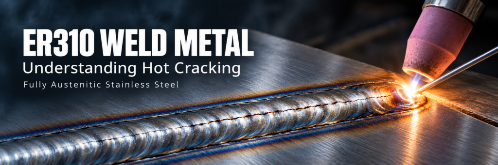
ER310 Weld Metal: Why Fully Austenitic Welds Can Hot Crack
ER310 weld metal can develop hot cracks because its fully austenitic solidification behavior allows weak, liquid-rich boundaries to persist while the weld contracts. When shrinkage and joint restraint impose more strain than those boundaries can accommodate, the solidifying metal separates.
This susceptibility does not mean ER310 inevitably cracks. It means that filler metal chemistry, dilution, weld pool shape, cleanliness, and restraint need careful control.
Understanding how these factors interact helps explain why a procedure can produce sound welds on one joint and centerline cracks on another.
What Makes ER310 Weld Metal Different?
ER310 is a chromium-nickel stainless steel filler metal commonly used to weld heat-resistant stainless steels of similar composition. Its alloy balance supports a fully austenitic weld deposit.
Many other austenitic stainless steel filler metals are designed to produce welds containing a small amount of delta ferrite. Depending on composition, their weld metal may begin solidification as ferrite before transforming largely to austenite.
ER310 typically follows a different path: austenite forms as the primary solidification phase.
That distinction matters because the path from liquid metal to solid weld affects cracking resistance—not simply the room-temperature microstructure.
A fully austenitic weld may have useful service properties while remaining comparatively sensitive to cracking during fabrication.
How Hot Cracking Develops in ER310
For ER310 weld metal, a central concern is solidification cracking. This occurs near the end of freezing, while the weld contains a connected solid structure separated by small amounts of residual liquid.
The mechanism involves three interacting conditions.
1. Austenite Dendrites Grow Into the Weld Pool
As the molten weld cools, branching crystals called dendrites grow from the fusion boundary toward the interior of the pool.
The developing dendrites form a solid framework. Between them, liquid remains.
The centerline can become particularly vulnerable because opposing solidification fronts meet there, leaving the last liquid to freeze in a narrow region.
2. The Remaining Liquid Becomes Enriched in Segregating Elements
Solid and liquid do not retain every element in the same proportions during freezing. Certain elements concentrate in the remaining liquid.
Sulfur and phosphorus are especially important because segregation can promote low-melting constituents and delay the development of strong boundaries.
The result can be a network of thin liquid films between solidifying dendrites.
Bulk chemical analysis does not reveal the full severity of this local enrichment. A small average impurity concentration can still matter when those impurities concentrate in the final liquid.
3. Contraction Pulls the Weak Boundaries Apart
The weld contracts as it solidifies and cools. Surrounding material and fixtures resist that movement.
If tensile strain develops while the interdendritic boundaries remain weak, the boundaries may separate before they can form a continuous, load-bearing structure. Restricted liquid feeding can make it harder to fill the opening.
ER310 solidification cracking therefore results from a vulnerable solidification structure combined with sufficient strain at the wrong moment.
Why Does Delta Ferrite Often Improve Cracking Resistance?
In many stainless steel weld metals, primary ferritic solidification improves resistance to solidification cracking.
Ferrite can accommodate certain impurity elements more readily than austenite. The resulting solidification structure can also make continuous, crack-sensitive liquid films less persistent.
However, it is misleading to treat ferrite as a universal additive that makes every weld safer.
Two distinctions matter:
- Solidification mode and retained ferrite are related but different. A room-temperature ferrite measurement does not fully describe how the weld froze.
- Fabrication performance must match service requirements. Changing filler metal to obtain ferrite can alter oxidation resistance, thermal stability, and other properties.
For ER310, the practical objective is usually to develop a sound procedure for the intended alloy system. Substituting another filler solely to increase ferrite requires an engineering assessment.
The Main Factors That Increase ER310 Hot Cracking Risk
| Factor | Why it matters | Practical control |
|---|---|---|
| Sulfur and phosphorus | Can enrich the last liquid and weaken solidifying boundaries | Review actual filler and base metal chemistry |
| Surface contamination | Can introduce harmful material into the pool | Clean the joint and filler metal |
| Uncontrolled dilution | Changes weld chemistry and solidification behavior | Control penetration, joint preparation, and filler addition |
| Unfavorable pool shape | Can concentrate final solidification along a weak centerline | Evaluate bead profile and parameter combinations |
| Excessive heat accumulation | Changes pool behavior, thermal strain, and distortion | Control heat input and interpass temperature |
| High joint restraint | Limits contraction and increases strain on weak boundaries | Plan fit-up, fixtures, and welding sequence |
| Poor crater termination | Leaves a vulnerable final-solidification region | Use controlled crater filling and arc termination |
Chemistry: Small Differences Can Affect Weldability
Two filler metal batches meeting the same classification do not necessarily have identical cracking behavior.
Actual sulfur, phosphorus, silicon, manganese, and other element levels can influence the solidification response. These effects depend on the overall composition rather than one element acting independently.
For demanding fabrication, review the actual material certificate alongside the base metal analysis. Classification compliance is essential, but it does not eliminate the need for procedure qualification.
Dilution: The Weld Is More Than the Filler Metal
The deposited weld contains melted base metal as well as filler.
Consequently, the composition of an ER310 wire or rod is not automatically the composition of the finished weld.
Dilution becomes particularly important in:
- Root passes with limited filler addition.
- Deep-penetration welds.
- Dissimilar metal joints.
- Repairs involving an existing weld deposit.
- Joints with variable preparation or fit-up.
An autogenous tack or root region may also solidify differently from a nearby region receiving sufficient filler metal.
Control filler addition and penetration together. Increasing either one without considering the other can produce an unintended weld composition.
Weld Pool Shape: Why the Centerline Is Vulnerable
A deep, narrow weld profile can encourage opposing columnar grains to meet along a concentrated centerline.
If the last liquid remains continuous in that region, contraction can open a crack along it.
Excessive travel speed can also create an elongated pool with an unfavorable final-solidification pattern. Simply increasing speed to reduce heat input may therefore introduce a different cracking risk.
A useful procedure balances penetration, travel speed, filler addition, and bead shape. Representative weld cross-sections help confirm whether that balance has been achieved.
How to Reduce Hot Cracking When Welding ER310
ER310 Use Controlled Heat Input
Relatively low, controlled heat input is commonly important when welding fully austenitic stainless steels. The objective is to manage the molten pool and thermal strain while maintaining complete fusion.
The lowest possible heat input is not automatically the best setting.
An excessively cold procedure can cause incomplete fusion or poor bead placement. An unsuitable combination of high speed and concentrated penetration can still produce a crack-sensitive pool.
Establish the operating range through a qualified welding procedure that represents the production joint.
ER310 Manage Interpass Temperature
In multipass welding, each pass changes the starting temperature for the next.
Uncontrolled heat accumulation can increase distortion and alter pool behavior. Measure interpass temperature consistently and allow cooling when required by the procedure.
There is no single interpass limit appropriate for every ER310 application. The limit should reflect the base material, joint thickness, service requirements, and qualification results.
ER310 Prefer Controlled Stringer Beads Where Appropriate
Controlled stringer beads can help limit individual pool size and make heat management more predictable.
Broad weaving may increase dwell time and complicate local heat control. However, narrow beads still require proper sidewall fusion and placement.
Bead technique should support a sound joint, not merely produce a smaller-looking weld.
ER310 Clean the Joint and Filler Metal
Remove oil, grease, paint, moisture, and other contamination before welding. Use suitable stainless steel preparation tools and protect cleaned surfaces from recontamination.
Keep ER310 rods and wire clean during storage and handling.
Shielding gas protects the molten metal from the surrounding atmosphere. It does not remove contaminants already present on the joint.
ER310 Reduce Avoidable Restraint
A perfectly clean weld can still crack if the joint imposes excessive strain during solidification.
Review:
- Root gap and alignment.
- Tack placement and condition.
- Fixture stiffness.
- Weld sequence.
- Local section changes.
- Freedom for controlled contraction.
Reducing restraint does not mean allowing uncontrolled movement. It means designing the assembly and sequence so contraction is accommodated without overstressing the solidifying weld.
Fill the Crater Before Ending the Arc
The weld crater is a common location for solidification cracks.
Abrupt termination can leave a concave, poorly fed region that freezes under contraction strain. Use the qualified crater-fill technique and maintain suitable shielding during termination.
Inspect tacks and stop-start regions carefully. Cracked tack welds should be addressed before they become part of the completed joint.
How to Investigate an ER310 Weld Crack
Start by recording where the crack occurs and when it is detected.
A longitudinal centerline crack or a crack in the termination crater suggests solidification cracking, but location alone does not prove the mechanism.
Cracks near the fusion boundary may involve liquation in the heat-affected zone or reheated weld metal. Cracking after extended high-temperature service requires a different investigation.
A practical sequence is:
- Map the crack relative to the weld centerline, fusion boundary, and stop-start locations.
- Review filler and base metal chemistry.
- Compare recorded parameters with the approved procedure.
- Examine restraint, fit-up, and welding sequence.
- Inspect representative cross-sections and, where necessary, the microstructure.
- Validate corrective changes before returning to production.
Visual inspection and liquid penetrant testing can reveal surface-breaking cracks. Internal examination requires a method suited to the joint and expected flaw orientation. No single inspection method detects every possible crack.
Common Misconceptions About ER310 Hot Cracking
“Zero Ferrite Means the Weld Is Defective”
A fully austenitic structure can be expected for ER310. Low ferrite alone is not evidence of a defective weld.
The relevant questions are whether the weld is sound and whether it meets the specified properties.
“Lower Amperage Always Prevents Cracking”
Amperage is only one variable. Voltage, travel speed, filler addition, penetration, and restraint also affect the result.
Lowering current without maintaining fusion can replace one defect with another.
“A Different Filler Will Solve the Problem”
A different filler may improve fabrication weldability while changing service performance.
Evaluate the complete joint requirements before substituting ER310.
“A Smooth Weld Surface Proves the Weld Is Sound”
Fine cracks may be difficult to see, and internal defects may have no obvious surface indication. Appearance should be supported by the required inspection and qualification.
Building a Reliable ER310 Welding Procedure
Reliable ER310 welding depends on controlling both sides of the cracking mechanism: the weak boundaries created during solidification and the strain imposed before those boundaries gain strength.
Start with verified materials and clean joints. Establish a parameter range that provides fusion without an unfavorable pool shape. Control dilution, heat accumulation, restraint, and crater termination. Then confirm performance on a representative joint.
That approach addresses why fully austenitic ER310 welds can hot crack—and provides a practical basis for preventing it.