

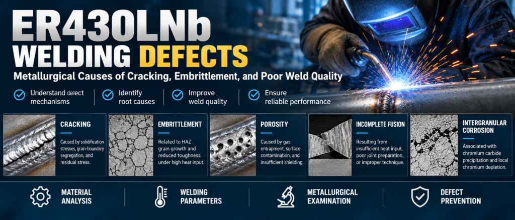
ER430LNb Welding Defects: Metallurgical Causes of Cracking, Embrittlement, and Poor Weld Quality
ER430LNb is a niobium-stabilized ferritic stainless steel welding filler metal associated with applications requiring oxidation resistance, thermal stability, and reliable welded joints. However, selecting an appropriate filler metal does not automatically guarantee defect-free welding. Cracking, embrittlement, porosity, incomplete fusion, and poor weld appearance can still occur when metallurgical characteristics interact with unsuitable welding conditions.
Understanding ER430LNb welding defects requires examining the relationship between chemical composition, solidification behavior, heat-affected zone (HAZ) evolution, residual stress, and corrosion exposure. These factors influence the integrity of the weld metal and the surrounding base material.
This article explains the principal metallurgical mechanisms behind ER430LNb welding problems, practical methods for identifying their causes, and process-control strategies for improving weld quality.
1. Understanding the Metallurgical Characteristics of ER430LNb
ER430LNb belongs to the category of niobium-stabilized ferritic stainless steel filler metals. Its performance depends on the actual chemical composition, the corresponding base metal, and the thermal history experienced during welding.
Three metallurgical factors are particularly important.
1.1 Niobium Stabilization and Carbon Control
Niobium has a strong affinity for carbon and can form niobium-rich carbides. Under suitable conditions, this stabilization mechanism reduces the amount of carbon available to form chromium carbides at grain boundaries.
Chromium carbide precipitation can locally deplete chromium from adjacent regions, reducing their resistance to certain corrosive environments. Appropriate stabilization can therefore help preserve corrosion resistance under relevant service conditions.
However, niobium does not eliminate every risk of carbide precipitation, embrittlement, or cracking. The result depends on the carbon and nitrogen levels, niobium content, thermal cycle, and microstructure of the welded joint.
1.2 Ferritic Microstructure and Grain Growth
Ferritic stainless steels can experience significant grain growth when exposed to elevated temperatures during welding. The coarse-grained HAZ may exhibit reduced toughness and ductility, particularly when the joint experiences substantial thermal exposure.
This behavior makes heat input an important variable. Excessive heat input or prolonged high-temperature exposure can promote grain coarsening, while unsuitable cooling conditions may contribute to undesirable microstructural changes.
1.3 Weld Metal and Base Metal Compatibility
Weld quality depends on more than the filler metal designation. Dilution from the base metal, surface contamination, shielding gas composition, and welding parameters can influence the final weld metal chemistry and microstructure.
Before diagnosing a defect, verify that ER430LNb is appropriate for the specific base metal, joint design, welding process, and service environment. The exact filler metal classification and chemical composition should be confirmed against the applicable product specification.
2. Common ER430LNb Welding Defects and Their Causes
2.1 Weld Cracking
Cracking is one of the most serious welding discontinuities because even a small crack can act as a stress concentrator and propagate under service loading.
Cracks may occur in the weld metal, at the weld toe, or within the heat-affected zone. Their location, orientation, and timing provide important clues about the underlying mechanism.
Potential metallurgical causes include:
Solidification shrinkage stresses exceeding the strength of the partially solidified weld metal.
Grain-boundary segregation or unfavorable local weld metal chemistry.
Coarse-grained or otherwise brittle microstructures.
Residual tensile stress caused by restrained thermal contraction.
Localized stress concentrations associated with joint geometry or incomplete fusion.
Solidification cracking generally develops during the final stages of weld metal solidification. By contrast, cracking that develops after cooling may involve residual stress, microstructural brittleness, or other mechanisms.
Hydrogen-assisted cracking should not automatically be assumed to be the dominant mechanism in ferritic stainless steel welds. Its likelihood depends on the specific material, microstructure, hydrogen exposure, and stress conditions.
Prevention strategies
Use a qualified welding procedure, maintain suitable joint preparation, and control heat input and travel speed. Avoid excessive restraint where practical, clean the joint thoroughly, and ensure that the weld crater is properly filled at the end of each pass.
If cracking occurs, determine its location and formation mechanism before selecting corrective measures. Simply increasing heat input or applying preheat without a metallurgical assessment may introduce additional problems.
2.2 Heat-Affected Zone Embrittlement
HAZ embrittlement can reduce the ability of a welded joint to tolerate impact, deformation, or thermal stress.
In ferritic stainless steels, the HAZ may experience substantial grain coarsening during welding. Large grains can reduce toughness, making the joint more susceptible to brittle fracture under unfavorable loading and temperature conditions.
The problem can become more significant when the component undergoes repeated heating and cooling, mechanical vibration, or thermal cycling.
Contributing factors include:
Excessive heat input.
Slow travel speed or prolonged high-temperature exposure.
Multiple welding passes that produce additional thermal cycles.
Inappropriate welding sequence or joint restraint.
A mismatch between the filler metal, base metal, and intended service conditions.
Prevention strategies
Select a suitable heat input range based on a qualified welding procedure. Avoid unnecessarily prolonged thermal exposure, and evaluate the effects of multipass welding on the HAZ.
Where toughness is critical, consider appropriate mechanical testing and metallographic examination. Post-weld heat treatment should not be applied automatically; its suitability must be established for the specific ferritic stainless steel grade and component requirements.
2.3 Intergranular Corrosion and Sensitization
Intergranular corrosion occurs when grain boundaries become more susceptible to preferential corrosion than the surrounding material.
In susceptible stainless steels, chromium carbide precipitation can create chromium-depleted regions adjacent to grain boundaries. If the local chromium concentration becomes insufficient to maintain the protective passive film in a particular environment, corrosion resistance may deteriorate.
Niobium stabilization can reduce this risk by preferentially binding carbon, but its effectiveness depends on material chemistry and thermal history.
The welding process may expose the base metal and HAZ to temperature ranges that promote microstructural changes. Subsequent exposure to moisture, corrosive condensates, or other aggressive environments can reveal weaknesses that were not obvious immediately after welding.
Prevention strategies
Confirm that the filler metal and base metal are metallurgically compatible. Control the welding thermal cycle, prevent surface contamination, and assess corrosion resistance when the component will operate in a demanding environment.
Where intergranular corrosion is suspected, use suitable metallographic methods and corrosion testing rather than relying solely on visual inspection.
2.4 Porosity and Gas-Related Defects
Porosity consists of gas cavities trapped within the solidifying weld metal. Unlike HAZ embrittlement, porosity is generally associated with gas entrapment and welding conditions rather than grain growth alone.
Potential causes include inadequate shielding gas coverage, contaminated surfaces, moisture, unstable gas flow, and unsuitable welding parameters.
Porosity may reduce the effective load-bearing area of a weld. Its impact depends on pore size, distribution, location, and the acceptance criteria applicable to the component.
Prevention strategies
Clean the base metal and filler material before welding. Verify shielding gas composition and flow rate, inspect hoses and connections, and protect the welding area from drafts that could disrupt gas coverage.
If porosity persists, examine the gas delivery system and surface preparation before making substantial changes to the welding parameters.
2.5 Incomplete Fusion and Incomplete Penetration
Incomplete fusion occurs when the weld metal fails to fuse properly with the base metal or a previous weld pass. Incomplete penetration occurs when the weld does not extend through the intended joint depth.
These defects are often process-related, although joint geometry and oxide contamination can contribute.
Common causes include insufficient heat input, excessive travel speed, an unsuitable torch angle, poor joint preparation, and inadequate cleaning between passes.
Prevention strategies
Verify the joint design and root opening. Adjust current, voltage, travel speed, and torch positioning within the qualified procedure. For multipass welding, remove surface oxides and other contaminants before depositing subsequent passes.
Visual inspection alone may not reveal internal fusion defects. Use an appropriate nondestructive testing method based on joint geometry, material thickness, and inspection requirements.
3. How Welding Parameters Influence ER430LNb Weld Quality
Welding parameters influence both defect formation and microstructural development. The objective is to maintain a stable welding process while limiting excessive thermal exposure and avoiding incomplete fusion.
3.1 Heat Input
Heat input affects the size and thermal history of the weld pool and HAZ. Excessive heat input can promote grain coarsening and increase the duration of high-temperature exposure.
Conversely, insufficient heat input may cause poor wetting, incomplete fusion, or inadequate penetration.
For arc welding, nominal heat input per unit length is commonly estimated as:
Heat input = (Voltage × Current × 60) / (Travel speed × 1000)
When voltage is expressed in volts, current in amperes, and travel speed in millimeters per minute, the result is expressed in kilojoules per millimeter before applying any process-efficiency factor.
The appropriate range depends on the welding process, joint design, material thickness, and qualified procedure. There is no single heat input value suitable for every ER430LNb application.
3.2 Shielding Gas
Shielding gas influences arc stability, metal transfer, weld pool behavior, and the final weld surface. An unsuitable gas mixture or unstable gas coverage can contribute to oxidation, porosity, and inconsistent bead formation.
Gas selection should be based on the welding process and the filler metal manufacturer’s technical recommendations. Gas flow should be sufficient to protect the weld pool without creating turbulence that draws surrounding air into the shielding zone.
3.3 Travel Speed and Weld Bead Geometry
Excessive travel speed may produce a narrow weld bead, inadequate penetration, or incomplete fusion. Very slow travel speed may increase heat input and promote excessive HAZ growth.
The appropriate travel speed should therefore be assessed together with current, voltage, joint geometry, and the required bead profile.
Consistent torch positioning and controlled crater filling also help reduce localized stress concentrations and end-of-weld cracking.
4. A Systematic Approach to ER430LNb Weld Defect Diagnosis
Effective defect prevention starts with determining the actual failure mechanism rather than changing several welding variables simultaneously.
A practical investigation can follow five steps.
Step 1: Identify the defect location.
Determine whether the defect lies in the weld metal, HAZ, weld toe, or root. Record its orientation, dimensions, and distance from the fusion boundary.
Step 2: Review material and process records.
Verify the filler metal designation, base metal grade, material certificates, shielding gas, joint preparation, and welding procedure. Check whether the actual welding parameters remained within the qualified range.
Step 3: Examine the defect using suitable inspection methods.
Visual inspection can identify surface-breaking cracks and bead irregularities. Liquid penetrant testing may help reveal surface-breaking discontinuities, while radiographic or ultrasonic testing may be appropriate for certain internal defects.
The inspection method should be selected according to the defect type, component geometry, and applicable acceptance criteria.
Step 4: Investigate the metallurgical mechanism.
Where necessary, use metallographic examination, hardness measurements, fracture-surface analysis, or chemical analysis to distinguish grain coarsening, intergranular degradation, solidification cracking, and process-related discontinuities.
Step 5: Validate corrective actions.
Modify the relevant welding variables through a controlled procedure review. Produce representative test welds and verify that the corrective measures address the identified mechanism without introducing new defects.
This approach is more reliable than assuming every crack or reduction in weld quality has the same cause.
5. Inspection and Quality Control for ER430LNb Welding
A robust quality-control plan should cover material verification, process control, weld inspection, and service requirements.
| Quality-control area | Key verification points |
|---|---|
| Material identification | Filler metal classification, chemical composition, and base metal compatibility |
| Surface preparation | Removal of oil, moisture, oxides, and other contaminants |
| Welding procedure | Qualified current, voltage, travel speed, shielding gas, and heat input |
| Weld appearance | Bead consistency, crater condition, undercut, and visible cracking |
| Internal integrity | Appropriate nondestructive testing based on component requirements |
| Metallurgical condition | HAZ grain structure, hardness, and corrosion behavior where relevant |
| Service performance | Thermal cycling, corrosion exposure, vibration, and mechanical loading |
Acceptance criteria should follow the applicable fabrication code, project specification, and service requirements. A visually acceptable weld is not necessarily free from internal defects or metallurgical degradation.
6. Frequently Asked Questions About ER430LNb Welding Defects
What causes cracking when welding ER430LNb?
Potential causes include solidification shrinkage, excessive restraint, unfavorable weld metal chemistry, brittle microstructures, and residual stress. The actual cause depends on where and when the crack forms.
Can ER430LNb prevent heat-affected zone embrittlement?
Niobium stabilization helps control certain carbide-related reactions, but it cannot eliminate grain coarsening or every source of embrittlement. Heat input, thermal cycles, base metal composition, and service conditions remain important.
Does higher heat input always improve weld quality?
No. Higher heat input may improve fusion in some circumstances but can also increase HAZ grain growth and high-temperature exposure. The correct range must balance penetration, fusion, and microstructural control.
How can intergranular corrosion be reduced?
Appropriate material selection, niobium stabilization, controlled welding thermal cycles, clean surfaces, and suitable corrosion testing can help reduce risk. Actual performance depends on the complete material and service environment.
What is the most effective way to prevent ER430LNb welding defects?
The most effective approach combines verified material compatibility, a qualified welding procedure, consistent surface preparation, stable shielding, controlled heat input, and inspection appropriate to the intended service.
Conclusion
ER430LNb welding defects can arise from interactions between ferritic stainless steel metallurgy, welding parameters, joint restraint, surface conditions, and service exposure. Cracking and embrittlement require particular attention because they may originate from microstructural changes even when the weld bead appears acceptable.
Niobium stabilization can help manage carbon-related metallurgical reactions, but it is not a substitute for appropriate welding procedure control and quality verification. Reliable results depend on identifying the defect mechanism, controlling the relevant process variables, and validating corrective actions through suitable inspection and testing.
For engineers and fabricators working with ER430LNb, a systematic approach to metallurgical analysis and welding quality control is essential for producing durable joints and reducing the risk of premature failure.