

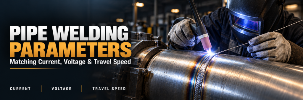
How to Set Pipe Welding Parameters: Matching Current, Voltage, and Travel Speed
Setting pipe welding parameters starts with understanding how current, voltage, and travel speed work together. Current influences electrode melting and penetration characteristics. Voltage affects arc behavior and bead shape. Travel speed determines how long the arc acts on each section of the joint.
The correct combination produces a controllable weld pool, adequate fusion, and a bead profile that meets the applicable acceptance criteria. An unsuitable combination can cause incomplete penetration, undercut, burn-through, or excessive heat input.
There is no universal setting for every pipe weld. Reliable parameter selection begins with the welding process, material, wall thickness, joint preparation, welding position, and an applicable welding procedure specification, or WPS.
What Are the Main Pipe Welding Parameters?
The three central variables are welding current, arc voltage, and travel speed. However, their effects depend on the process and the conditions around the arc.
| Parameter | Main influence | Problems when poorly matched |
|---|---|---|
| Welding current | Electrode melting, arc force, and penetration characteristics | Incomplete fusion, excessive penetration, or an oversized weld pool |
| Arc voltage | Arc length, arc distribution, and bead profile | Unstable arc, poor bead shape, or undercut |
| Travel speed | Energy and deposited metal per unit length | Burn-through, excessive reinforcement, or insufficient fusion |
Other variables must remain controlled while these settings are adjusted. Electrode diameter, polarity, shielding gas, torch angle, wire extension, and joint fit-up can all change the result.
A parameter combination that works on one joint may perform poorly when the root gap or welding position changes.
Start with the Welding Process
The relationship between machine settings and actual welding conditions differs between processes.
GTAW: Set Current and Control Arc Length
Gas tungsten arc welding, also called TIG welding, generally uses a constant-current power source. The operator sets the current and controls arc length through torch positioning.
Voltage changes as arc length changes. Consequently, voltage is usually an observed process value in manual GTAW rather than an independently selected setting.
For a stable root pass:
Select current within the WPS range.
Maintain a short, consistent arc appropriate to the joint.
Coordinate travel speed with filler addition.
Keep the torch angle and shielding arrangement consistent.
Lengthening the arc to compensate for poor fit-up can spread the heat and make root control more difficult.
SMAW: Match Current to the Electrode and Position
Shielded metal arc welding, or stick welding, also typically uses a constant-current power source.
Current selection depends on the electrode classification, diameter, polarity, welding position, and procedure requirements. Arc voltage varies mainly with the arc length maintained by the welder.
Too little current can cause sticking and poor fusion. Excessive current can make the pool difficult to control, particularly in overhead or vertical sections of a fixed pipe joint.
GMAW and FCAW: Coordinate Wire Feed Speed and Voltage
In conventional constant-voltage gas metal arc welding and many flux-cored applications, wire feed speed strongly influences welding current. Voltage is selected to establish suitable arc behavior for the wire, gas, and transfer mode.
Increasing wire feed speed without matching voltage and travel speed can produce an unstable arc or excessive deposited metal.
Pulsed and synergic equipment may coordinate several variables automatically. Even then, the selected program, wire, shielding gas, and operating range must match the qualified procedure.
Check the Joint Before Changing the Settings
Parameter adjustment cannot reliably compensate for inconsistent joint preparation.
Before welding, confirm:
Pipe material and wall thickness
Bevel angle and root face
Root gap and internal alignment
Surface cleanliness
Electrode or filler metal classification and diameter
Required preheat and interpass temperature
Shielding and backing gas arrangements, where applicable
For example, a wider root gap can increase burn-through risk at settings that previously produced acceptable penetration. A thicker root face may require a different balance of current and travel speed.
If fit-up changes from joint to joint, the welding response will change even when the machine settings remain identical.
How to Match Welding Current to Travel Speed
Current and travel speed should be adjusted as a pair because they affect both fusion and weld pool size.
Higher current may support faster travel, but only while the arc continues to fuse the root and sidewalls adequately. Increasing speed too far can produce a narrow bead with insufficient fusion.
Reducing travel speed increases the time the arc acts on a given length of joint. However, slower travel does not always produce deeper penetration. An oversized pool may flow ahead of the arc and interfere with direct fusion at the leading edge.
Use these observations to guide adjustments:
| Weld observation | What to check first |
|---|---|
| Small pool with poor edge melting | Current, travel speed, arc placement, and joint preparation |
| Large, sagging pool | Excessive current, slow travel, or excessive deposition |
| Narrow bead with poor sidewall fusion | Travel speed, torch angle, arc distribution, and bevel access |
| Excessive reinforcement | Deposition rate relative to travel speed |
| Inconsistent root penetration | Root gap, root face, arc length, current, and travel consistency |
These are diagnostic starting points. A visible symptom can have several causes, so inspect the joint and technique before changing a setting.
How to Match Voltage to the Welding Process
Voltage should not be treated as a universal penetration control.
In manual GTAW and SMAW, an increase in measured voltage often reflects a longer arc. In conventional constant-voltage wire welding, changing the voltage setting alters arc behavior and usually changes bead width and profile.
For wire processes, assess voltage together with:
Wire feed speed
Wire diameter
Shielding gas composition
Metal transfer mode
Contact-tip-to-work distance
Welding position
A wider bead does not automatically mean better fusion. Increasing voltage may spread the arc without correcting poor sidewall access or unsuitable torch positioning.
Always evaluate the complete bead profile and the required inspection results.
Calculate Arc Energy to Understand the Balance
Arc energy helps compare combinations of current, voltage, and travel speed.
For steady welding conditions:
Arc energy (kJ/mm) = [Voltage × Current × 60] ÷ [Travel speed (mm/min) × 1,000]
Consider an illustrative calculation:
Voltage: 12 V
Current: 100 A
Travel speed: 100 mm/min
The resulting arc energy is:
(12 × 100 × 60) ÷ (100 × 1,000) = 0.72 kJ/mm
If travel speed increases to 150 mm/min while current and voltage remain unchanged:
(12 × 100 × 60) ÷ (150 × 1,000) = 0.48 kJ/mm
That is approximately a 33% reduction in arc energy per unit length.
These values demonstrate the calculation; they are not recommended settings for a particular pipe joint.
Arc Energy and Heat Input Are Different
Arc energy represents electrical energy per unit weld length. Where the applicable calculation method requires it, heat input incorporates a process efficiency factor:
Heat input = Arc energy × Thermal efficiency factor
Use the calculation method required by the governing specification. For pulsed or waveform-controlled welding, multiplying average current by average voltage may not accurately represent average power. Appropriate equipment measurements may be necessary.
Also, identical arc energy values do not guarantee identical penetration or metallurgical results. Arc concentration, polarity, process efficiency, and metal transfer behavior still matter.
Set Parameters Separately for Each Weld Pass
A pipe joint normally needs different operating conditions as the groove fills.
Pipe welding Root Pass
The root pass requires control of penetration, internal profile, and edge fusion.
Focus on consistent fit-up, controlled arc length, balanced filler addition, and suitable travel speed. Increasing current alone may enlarge the root opening or cause excessive penetration.
Where back purging is required, verify that protection is established before welding.
Pipe welding Hot Pass
Where the procedure includes a hot pass, its settings must suit the existing root profile and remaining groove geometry.
Do not assume that a hotter pass will correct root defects. Defects requiring removal should be addressed through the applicable repair procedure.
Pipe welding Fill Passes
Fill passes require adequate sidewall fusion and controlled deposition.
Match current, voltage where adjustable, and travel speed to the available groove width. Clean between passes and monitor interpass temperature.
Pipe welding Cap Pass
The cap must achieve the specified contour and toe transition without excessive reinforcement or undercut.
Bead placement, travel speed, and pool size become particularly important near the groove edges. Confirm adequate fill before attempting the final cap.
Account for Pipe Welding Position
Settings that work on a rotating pipe may be unsuitable for a fixed pipe.
As the torch moves around a fixed joint, gravity changes how the molten metal behaves. A manageable pool in the flat section may sag in the overhead section.
Mechanized systems may use position-specific parameter sectors. Manual welders also adapt technique and operating conditions within the WPS.
Avoid making large, unverified parameter changes simply to maintain a constant travel speed around the circumference.
Pipe welding Use a Controlled Parameter Adjustment Sequence
A consistent adjustment method makes troubleshooting more efficient.
Confirm the WPS and joint conditions. Check fit-up, cleanliness, consumables, polarity, and temperature.
Establish a stable arc. Resolve erratic feeding, poor electrical connections, or shielding problems.
Set current or wire feed speed. Choose a suitable value within the permitted range.
Set voltage where applicable. Match it to the wire, gas, transfer mode, and current level.
Adjust travel speed. Aim for stable fusion and the required bead dimensions.
Inspect the result. Assess root profile, bead contour, and any required test results.
Record the verified conditions. Include actual welding values and relevant joint details.
Change one variable at a time during troubleshooting where practical. Once the cause is understood, verify the final combination as a complete operating condition.
Build a Repeatable Pipe Welding Setup
Effective pipe welding parameter selection combines a qualified procedure, consistent joint preparation, stable technique, and measured operating conditions.
Start with the required process and pass type. Match current, voltage behavior, and travel speed to the joint. Verify fusion and bead profile, then document the combination that meets the procedure and inspection requirements.