

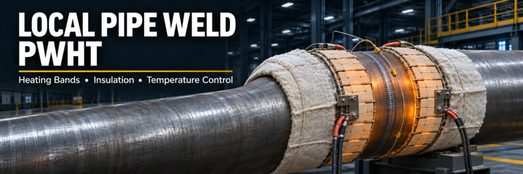
Local Pipe Weld PWHT: Band Control Guide
Local Pipe Weld PWHT requires more than bringing a welded joint to a specified temperature. A successful treatment depends on how heat moves through the pipe wall, around the circumference, and into the surrounding material. Correct heating bands, sufficient insulation, and reliable temperature monitoring help achieve the required thermal cycle while limiting harmful temperature differences.
This guide explains how to plan the heated area, manage heat loss, position thermocouples, and evaluate temperature records for circumferential pipe welds.
Local Pipe Weld PWHT: Understanding the Three Bands
Before installing heaters, distinguish between the soak band, heated band, and gradient control band. These areas serve different purposes and should be identified separately in the approved procedure.
The soak band is the volume of material that must remain within the specified treatment temperature range for the required holding period. It includes the weld and the adjacent material required by the applicable specification. Its requirement extends through the wall thickness.
The heated band is the area where the heat source is applied. It generally extends beyond the soak band so that heat losses near the heater edges do not prevent the required material from reaching treatment temperature.
The gradient control band extends across the heated region and adjacent material to manage the transition toward cooler pipe. Insulation, supplementary heaters, or a combination of both may provide this control.
For Local Pipe Weld PWHT, these bands form a coordinated thermal arrangement. A heater layout that reaches the target temperature at the weld center can still be inadequate if the soak-band edges remain too cold or the surrounding pipe cools too abruptly.
Local Pipe Weld PWHT Heating Band Design
Select heating-band dimensions using the governing construction or repair requirements, material specification, and approved heat-treatment procedure. Avoid applying a single width formula to every pipe.
Factors that affect the layout include:
Pipe diameter and wall thickness.
Weld width and joint geometry.
Material thermal properties.
Differences in thickness across the joint.
Nearby flanges, branches, supports, or attachments.
Heater capacity and available control zones.
Pipe orientation and environmental conditions.
Thick walls require particular attention because an acceptable outside-surface temperature does not automatically demonstrate an acceptable inside-surface temperature.
For large diameters or uneven thermal mass, independently controlled heater zones can help balance the temperature distribution. Each zone needs suitable temperature feedback and sufficient power to follow the planned cycle.
Local Pipe Weld PWHT Insulation Band Planning
Insulation reduces heat loss and helps create a gradual temperature transition beyond the heated area. Its effectiveness depends on coverage, thickness, condition, and installation quality.
Extend insulation to the boundaries established by the approved procedure. Simply covering the heater elements may leave the adjacent pipe exposed to excessive cooling.
Inspect the arrangement for open seams, loose edges, compressed sections, and gaps around protrusions. These details can create localized cold areas even when the overall insulation width appears adequate.
In Local Pipe Weld PWHT, insulation should be treated as a process variable. Changing its thickness or coverage can alter the temperature profile, heater demand, and cooling behavior.
Environmental exposure also matters. Wind can increase external heat loss, while airflow through an open pipe can remove heat internally. Where needed, use approved wind protection or suitable internal airflow controls. Any internal barrier must be appropriate for the equipment and work conditions.
Local Pipe Weld PWHT Temperature Gradient Control
Temperature gradients describe spatial temperature differences. They should be evaluated separately from heating and cooling rates, which describe temperature changes over time.
Three directions require attention:
Axial gradients: Temperature changes along the pipe, moving away from the weld. A narrow heated or insulated area can produce a steep transition between hot and cold material.
Circumferential gradients: Temperature differences around the pipe. Uneven heater contact, asymmetric attachments, and different heat losses can leave one sector hotter than another.
Through-wall gradients: Temperature differences between the outside and inside surfaces. These are especially relevant when thick pipe is heated externally.
The objective is to meet the applicable limits throughout the cycle. Increasing the temperature setpoint alone is not a reliable correction for a cold location because it may overheat another part of the joint.
Local Pipe Weld PWHT Thermocouples and Cycle Verification
Thermocouples provide evidence of the temperatures reached at their attachment points. Their quantity and locations should follow the approved procedure and reflect the geometry and expected hot and cold areas.
Control thermocouples regulate heater output. Monitoring thermocouples provide additional measurements that help assess temperature distribution.
Depending on the procedure, monitoring locations may include the weld region, soak-band boundaries, different circumferential positions, and locations used to evaluate axial temperature changes. Through-wall temperature verification may require additional measurements or a justified engineering method.
For Local Pipe Weld PWHT, a smooth controller trace is only one part of verification. The complete record must demonstrate that the required locations satisfied the specified heating rate, holding temperature, holding time, and cooling requirements.
Before starting, verify sensor identification, attachment, channel assignments, instrument calibration, and recording functions. Poor sensor contact can produce misleading readings and inappropriate heater response.
Begin the holding period only when the required monitored locations meet the approved temperature criteria.
Troubleshooting Uneven Temperatures
When readings diverge, investigate the physical arrangement before changing controller settings.
| Observation | Possible cause | Item to check |
|---|---|---|
| One circumferential sector stays cold | Local heat loss or inadequate heater output | Insulation gaps, heater condition, zone capacity |
| One location becomes unusually hot | Excessive local input or unsuitable control feedback | Heater layout and thermocouple attachment |
| Soak-band edges remain cold | Insufficient heat coverage or excessive edge losses | Heated-band width and insulation arrangement |
| Temperature falls unexpectedly | Power interruption, airflow, or heater failure | Electrical supply, heater continuity, exposure |
| One reading changes abruptly | Sensor or connection problem | Thermocouple attachment, leads, and channel |
Follow the approved response for temperature excursions. A lost holding period or interrupted cycle should not be accepted solely because the final temperature eventually returned to the setpoint.
Final Acceptance Checklist
Review the completed treatment against the procedure:
Confirm the specified band dimensions and heater zones.
Check that required temperature channels remained valid.
Verify heating and cooling rates where limits apply.
Confirm the holding temperature range and duration.
Review interruptions, excursions, and corrective actions.
Complete required inspection, testing, and documentation.
Reliable Local Pipe Weld PWHT combines a suitable thermal layout with verified execution. Heating bands supply energy, insulation manages heat loss, and temperature measurements demonstrate whether the required material received the specified treatment.