

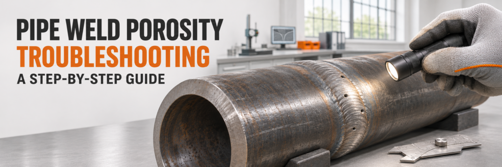
Recurring Porosity in Pipe Welds: A Step-by-Step Troubleshooting Guide
Pipe Weld Porosity Troubleshooting starts with identifying when and where gas cavities appear, rather than repeatedly grinding out the same defect. If pores return after repair, the original source of contamination or inadequate protection may still be present. A structured investigation helps isolate the cause, reduce unnecessary rework, and establish repeatable welding conditions.
Porosity forms when gas becomes trapped as weld metal solidifies. It may appear as visible surface holes, isolated internal pores, clusters, or elongated cavities. Its significance depends on the size, distribution, location, and acceptance criteria for the joint.
Step 1: Begin Pipe Weld Porosity Troubleshooting with a Defect Map
Before changing equipment settings, record the defect location and the conditions under which it occurred. Include the welding process, pipe material, joint position, pass number, consumable batch, and relevant inspection results.
Look for patterns around the pipe circumference and through the weld thickness.
| Observed pattern | Possible investigation direction |
|---|---|
| Pores concentrated at starts | Gas delivery delay, contaminated start area, or starting technique |
| Pores around restarts | Inadequate cleaning or inconsistent restart protection |
| Random pores throughout a pass | Persistent contamination or unstable shielding |
| Defects near tack welds | Tack quality, preparation, or contamination |
| Recurrence at one clock position | Access, torch angle, airflow, or local joint conditions |
| Problems beginning after a change | Gas supply, consumable, equipment, or procedure changes |
These patterns guide the investigation; they do not prove a particular cause.
Pipe Weld Porosity Troubleshooting: Confirm the Imperfection Type
Do not assume every cavity is gas porosity. Slag inclusions, incomplete fusion, and crater shrinkage require different corrective actions.
Visual examination identifies surface-breaking indications but cannot establish the full internal condition. Use the inspection method specified for the joint and obtain a qualified interpretation where the indication type is uncertain.
Step 2: Focus Pipe Weld Porosity Troubleshooting on Cleanliness
Inspect the bevel, root face, adjacent surfaces, and accessible pipe interior. Oil, grease, moisture, rust, and unsuitable coatings can introduce gas-forming contamination into the weld pool.
Clean beyond the immediate groove so that heating does not draw nearby contamination into the joint. Use preparation methods compatible with the pipe material and service requirements.
Check the following:
- Cutting fluids remaining after machining.
- Moisture trapped near the root or inside the pipe.
- Marking compounds and coating residues near the groove.
- Contaminated grinding tools or cleaning cloths.
- Dirty filler rods or exposed welding wire.
- Residue introduced during earlier repair operations.
Allow approved cleaning agents to evaporate completely before welding. Do not use chlorinated solvents near welding operations.
For stainless steel, use suitable dedicated preparation tools to avoid introducing embedded carbon-steel contamination.
Step 3: Use Pipe Weld Porosity Troubleshooting to Check Gas Protection
For gas-shielded processes, trace the gas path from the supply to the torch. A regulator reading alone does not establish adequate protection at the weld.
Inspect hoses, fittings, seals, valves, diffusers, and nozzles. Check for damaged connections, restrictions, spatter buildup, and incorrect assembly. Verify delivery under actual operating conditions using a suitable checking method.
Avoid automatically increasing the flow. Too little gas can leave the weld pool exposed, while excessive flow can create turbulence and draw air into the shielding envelope.
Check nearby doors, fans, extraction equipment, and outdoor wind. Use appropriate screens or positioning adjustments while maintaining required ventilation.
Pipe Weld Porosity Troubleshooting for Root-Side Protection
Where the procedure requires backing gas, inspect the purge system separately from torch shielding.
Check purge dams, joint seals, inlet placement, venting, and any specified oxygen measurements. An apparently stable torch shield cannot compensate for inadequate protection inside the pipe.
Root discoloration or sugaring may indicate oxidation, but it is not the same imperfection as porosity. Evaluate both conditions against the applicable requirements rather than treating one as proof of the other.
Step 4: Extend Porosity Troubleshooting to Consumables and Equipment
Confirm that filler metal, electrode classification, shielding gas, and polarity match the welding procedure specification, or WPS.
For solid-wire processes, inspect wire condition, feed stability, drive rolls, liners, and contact tips. Dirty or corroded wire can carry contamination into the joint.
For coated electrodes and flux-bearing consumables, verify storage and exposure conditions. Follow the applicable handling instructions. Do not apply a single drying or rebaking schedule to every consumable type.
For TIG welding, inspect the tungsten electrode and filler rod. If the tungsten contacts the weld pool or filler, restore its condition before continuing. Confirm that the torch components are correctly fitted and suitable for the joint access.
A controlled trial using known-condition consumables can help isolate a suspected supply issue. Record the change so the result remains traceable.
Step 5: Keep Porosity Troubleshooting Within the WPS
Once cleanliness, gas delivery, and equipment condition are verified, review technique and operating parameters.
Check arc length, voltage, current, travel speed, torch angle, and the relevant electrode or nozzle distance. Excessive arc length or poor torch positioning can weaken protection and destabilize the process.
Pipe geometry makes consistency difficult. As the welder moves around the circumference, access and hand position change. Compare the technique at defective locations with the technique used on acceptable sections.
Change one variable at a time within the permitted procedure range. Increasing heat input is not a universal cure: it can introduce distortion, burn-through, or other unacceptable conditions without eliminating the contamination source.
Step 6: Complete Porosity Troubleshooting with Repair Verification
Determine whether repair is necessary using the applicable acceptance criteria. Not every pore requires rejection, and a clean surface does not guarantee an acceptable internal weld.
Where repair is required:
- Establish the affected area using the specified inspection.
- Remove unacceptable material using an approved method.
- Examine the excavation as required by the repair procedure.
- Clean and prepare the repair area.
- Correct the suspected cause before rewelding.
- Reinspect using the required method and acceptance criteria.
Repeatedly depositing new metal over a contaminated excavation can reproduce the original problem.
Verify the corrective action under representative conditions. A short acceptable trial is useful evidence, but recurring production defects may require additional monitoring across relevant positions, passes, or shifts.
Pipe Weld Porosity Troubleshooting is most effective when each correction is linked to recorded evidence. Mapping the defect, eliminating contamination, verifying protection, and checking technique in sequence turns repeated repair into a controlled investigation.