

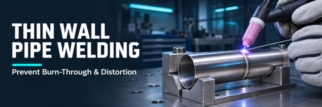
Thin Wall Pipe Welding: Prevent Burn-Through
Thin Wall Pipe Welding requires precise control of fit-up, arc energy, and travel speed. On small-diameter tubing, a slight gap or a brief pause can turn a controlled weld pool into a hole. Uneven heating can also pull the joint out of alignment or leave the tube oval. Preventing these defects starts before the arc is struck, with accurate preparation and a welding procedure matched to the material, wall thickness, and service requirements.
This guide explains how to reduce burn-through and distortion while maintaining the fusion needed for a sound joint.
Why Thin Wall Pipe Welding Causes Burn-Through and Distortion
Burn-through occurs when the molten joint loses support and opens into a hole. Common triggers include excessive local heating, an oversized root gap, inconsistent wall thickness, and slow travel.
Distortion develops as heated metal expands and subsequently contracts during cooling. Around a small pipe circumference, uneven contraction can cause angular misalignment, shortening, or loss of roundness.
These problems share several causes, but their solutions are not identical. Lowering current may help prevent a hole, yet insufficient current can produce incomplete fusion. Similarly, heavy clamping may limit visible movement while increasing restraint and residual stress.
The objective is sufficient fusion with controlled heat distribution.
Thin Wall Welding Starts With Consistent Fit-Up
Cut pipe ends square and remove burrs from both the inside and outside edges. Check alignment around the entire circumference before tacking.
An uneven gap creates changing welding conditions: one section may fuse normally while another requires extra filler and slower travel. That additional dwell time increases the risk of local overheating.
Prepare the joint according to the welding procedure. A close-fitting square butt joint may suit certain thin tubing applications, while others require a specified gap or edge preparation. Do not assume that either zero gap or a beveled edge is universally correct.
Clean the joint and filler metal thoroughly. Remove oil, moisture, oxides, and other contamination using methods suitable for the alloy.
Selecting a Process for Thin Wall Welding
TIG welding is often suitable for small-diameter, thin-wall tubing because it provides precise arc placement and independent control of filler addition. Current control can help the operator respond as the joint heats up.
Pulsed TIG can provide useful control, but its effectiveness depends on the complete waveform and welding technique. Peak current, background current, pulse duration, and travel speed all influence the result.
MIG welding can also work where access, equipment capability, and a qualified procedure support it. Process selection should account for minimum stable output, transfer mode, joint position, and required root quality.
For repetitive production, orbital welding may improve consistency when preparation, alignment, and programmed parameters are tightly controlled.
Thin Wall Welding Settings Must Match the Joint
There is no universal amperage setting for every thin pipe. Alloy, wall thickness, diameter, joint geometry, welding position, and equipment characteristics all matter.
Develop settings on a representative test joint:
- Match the production material, wall thickness, and joint preparation.
- Establish stable fusion without allowing the pool to widen excessively.
- Adjust current and travel speed together.
- Examine the root as well as the external bead.
- Record the successful parameters and fit-up conditions.
Avoid choosing settings solely because the bead looks smooth. A neat surface can conceal incomplete root fusion or excessive internal penetration.
Controlling Heat During Thin Wall Welding
Maintain a short, stable arc appropriate to the process. In TIG welding, an unnecessarily long arc raises voltage and can spread heat beyond the intended joint area.
Use a controlled travel speed and avoid lingering over one location. If the weld pool becomes noticeably larger as the circumference progresses, reassess heat accumulation before continuing.
Keep the bead within the required dimensions. Excessive reinforcement adds material, welding time, and shrinkage without automatically improving joint performance.
Where filler is required, select a compatible alloy and a diameter suited to the joint. Oversized filler can interrupt the pool and encourage prolonged heating.
At the end of a TIG weld, use an appropriate current downslope and crater-filling technique. Abrupt termination can leave a crater defect, while lingering at full current can overheat the closing section.
Reducing Distortion in Thin Wall Weld
Support the pipe so its weight does not load the joint. Alignment fixtures should hold the intended geometry without forcing poorly prepared parts together.
Place sound tacks in a balanced arrangement around the circumference. Check alignment after tacking because the tacks themselves can move the joint.
Where permitted by the procedure, a balanced sequence of short sections can help distribute heating. For some applications, however, a continuous circumferential pass provides better consistency and fewer restarts. Choose the sequence through representative trials.
Additional controls include:
- Limiting weld size to the specified requirement.
- Monitoring interpass temperature when multiple passes are needed.
- Allowing cooling as required by the procedure.
- Using suitable backing or heat sinks only when compatible with the joint.
- Checking dimensions after the assembly has cooled.
Do not introduce water quenching as an improvised distortion remedy. Cooling practices must suit the material and approved fabrication procedure.
Shielding and Purging for Thin Wall Weld
Shielding gas protects the molten weld from atmospheric contamination. Check gas coverage, torch condition, leaks, and drafts before changing electrical settings to solve an apparent welding problem.
More gas is not always better. Excessive flow can create turbulence and draw air into the shielding envelope.
For stainless steel and other oxidation-sensitive materials, internal purging may be necessary to achieve the required root condition. Establish the specified atmosphere before welding and maintain protection for the required period.
Provide an outlet for purge gas. Excessive internal pressure can disturb the molten root, particularly as the joint closes.
Use measurable acceptance criteria where required. Gas flow alone does not confirm that oxygen has been displaced sufficiently.
Troubleshooting Thin Wall Weld Defects
| Observed problem | Possible causes | Practical response |
|---|---|---|
| A hole forms at one location | Wide gap, thin edge, excessive dwell | Correct preparation and reassess local heat input |
| The pool grows near completion | Accumulating heat, slowing travel | Adjust technique and parameters within the procedure |
| The joint bends after cooling | Uneven heating, poor support, unbalanced sequence | Improve support and validate the welding sequence |
| The root is heavily oxidized | Inadequate purging or air leakage | Check seals, venting, and purge acceptance criteria |
| The bead looks smooth but lacks fusion | Insufficient energy or poor arc placement | Verify fusion on a representative test joint |
| Internal penetration is excessive | Excess heat, unsuitable gap, inconsistent travel | Review fit-up and welding parameters together |
Change one variable at a time during development whenever practical. Otherwise, it becomes difficult to identify which adjustment improved the result.
Inspect the Finished Joint Before Acceptance
Inspect both the external weld and the internal root where accessible. Look for cracks, undercut, oxidation, excessive penetration, and inconsistent bead shape. Confirm alignment and roundness after cooling.
For procedure development, sectioning representative test welds can reveal fusion problems that visual inspection misses. Production inspection and any leak or pressure testing should follow the applicable specification.
Reliable Thin Wall Pipe Welding depends on repeatable preparation, stable fusion, controlled heating, and verified results. Treat fit-up and welding technique as one connected process: consistent inputs make sound, dimensionally accurate joints easier to reproduce