

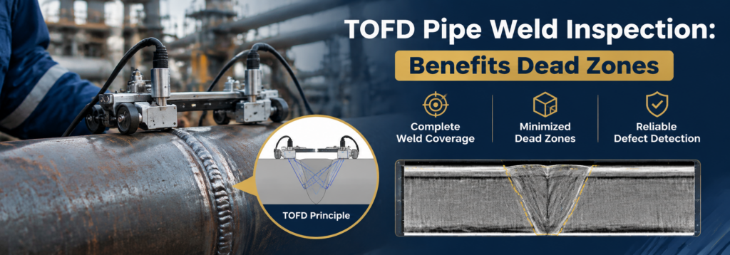
TOFD Pipe Weld Inspection uses ultrasonic diffraction signals to detect and size discontinuities in welded piping. Its main strength is through-wall flaw sizing, particularly when signals from both flaw tips can be resolved. However, lateral-wave interference, back-wall signals, pipe geometry, and material structure can restrict coverage. A reliable examination therefore requires a validated scan plan and complementary testing where necessary.
How TOFD Pipe Weld Inspection Works
Time-of-flight diffraction uses a transmitting probe and a receiving probe, typically positioned on opposite sides of the weld. The transmitter sends ultrasonic energy into the material, while the receiver records signals travelling along different paths.
In a typical examination, the recorded data may include:
- A lateral wave travelling near the scanning surface.
- Diffracted signals originating from discontinuity tips.
- A back-wall reflection from the opposite surface.
- Additional signals caused by geometry, mode conversion, or material structure.
An encoded scan combines successive ultrasonic records into an image of the weld along its length. Analysts evaluate signal arrival times and patterns to locate indications and estimate their dimensions.
Unlike methods that size flaws primarily from reflected amplitude, diffraction-based sizing relies largely on travel time. Nevertheless, signal amplitude and signal-to-noise ratio remain important: an unresolved tip signal cannot provide a reliable measurement.
TOFD Pipe Weld Inspection: Main Advantages
Through-wall sizing
When upper-tip and lower-tip signals are identifiable, their calculated depths can be used to estimate flaw height. This information can support engineering assessments, provided measurement uncertainty and the applicable assessment requirements are considered.
Recorded examination data
Encoded inspection produces a reviewable record. Stored data can support independent interpretation, quality audits, and comparisons during subsequent examinations.
Efficient scanning
A suitable probe arrangement can examine a substantial weld volume during a scan. Thick sections or demanding coverage requirements may require multiple inspection zones rather than a single probe pair.
Reduced dependence on specular reflection
Diffraction can reveal discontinuities that do not direct a strong reflected signal back toward a conventional pulse-echo probe. However, flaw orientation still affects detectability; the technique is not equally sensitive to every discontinuity.
No ionizing radiation
The ultrasonic examination itself does not require a radiation exclusion area. This can simplify coordination with nearby work, although access, surface preparation, and site safety requirements still apply.
TOFD Pipe Weld Inspection: Understanding Near-Surface Dead Zones
A dead zone is a region in which relevant discontinuity signals may be obscured by another signal. It should be treated as a coverage limitation, not as proof that the material is free from flaws.
Lateral-Wave Interference at the Scanning Surface
Near the scanning surface, a shallow flaw-tip signal may arrive too close to the lateral wave to be distinguished clearly. The signals can overlap, reducing detection or sizing capability.
There is no universal dead-zone depth applicable to every setup. Its extent depends on factors including:
- Probe centre separation.
- Ultrasonic pulse duration and bandwidth.
- Material sound velocity.
- Component geometry.
- Acquisition settings and signal quality.
A fixed statement such as “the first 3 mm cannot be inspected” is therefore unsuitable without supporting setup-specific evidence.
Surface-breaking flaws may also disturb the lateral wave. Such disturbances can provide useful information, but they do not automatically establish dependable detection and sizing of every shallow flaw.
Back-Wall Interference at the Opposite Surface
A second restricted region can occur near the back wall, where diffraction signals overlap the back-wall response.
For an externally scanned pipe, this limitation is particularly relevant to the internal surface and weld-root region. Root geometry and internal mismatch may add signals that complicate interpretation.
This distinction matters: the scanning-surface dead zone and the opposite-surface dead zone affect different locations and may require different complementary examination arrangements.
Practical Limitations Beyond Dead Zones
Pipe Diameter and Curvature
Pipe curvature affects probe contact, sound paths, and the relationship between measured travel time and calculated position. Its influence depends on pipe diameter, wall thickness, weld orientation, and probe arrangement.
A setup validated on a flat plate should not automatically be accepted for a small-diameter pipe. Representative geometry and appropriate calibration are necessary.
Access and Surface Condition
The conventional arrangement generally requires scanning access on both sides of the weld. Nearby fittings, supports, weld reinforcement, coatings, or rough surfaces can restrict probe movement or disrupt coupling.
Loss of coupling can produce missing or misleading data. Scanning speed should therefore remain consistent with reliable acquisition and adequate coverage.
Material Structure
Coarse-grained, anisotropic, or strongly attenuating materials can scatter and distort ultrasonic signals. Austenitic and dissimilar-metal welds may require specialized procedures and additional validation.
Successful examination of a carbon-steel weld does not establish equivalent performance in a different material.
Flaw Characterization and Position
Diffraction data can support depth and height measurements, but a single scan may not establish the exact lateral position, orientation, or nature of every indication.
Small volumetric discontinuities and closely spaced flaws can also be difficult to resolve. Additional scans or another ultrasonic technique may be needed to clarify the result.
Planning TOFD Pipe Weld Inspection for Complete Coverage
The objective is to demonstrate coverage of the required examination volume and sensitivity to relevant flaws.
A practical inspection plan should address the following:
- Define the examination requirements. Establish the governing specification, weld geometry, material, examination volume, and acceptance criteria.
- Select and validate the setup. Choose probes, separation, inspection zones, and acquisition settings appropriate to the component.
- Establish restricted regions. Evaluate near-surface and back-wall limitations using suitable representative reflectors or demonstration specimens.
- Add complementary coverage. Use qualified pulse-echo or phased-array techniques where they demonstrate the required sensitivity.
- Assess surface examination needs. Magnetic particle testing may suit ferromagnetic materials; penetrant testing may reveal surface-breaking discontinuities on suitable nonporous surfaces.
- Document the result. Record calibration, coverage, data quality, indications, sizing uncertainty, and any unexamined regions.
Surface methods do not replace subsurface ultrasonic coverage. Likewise, adding phased-array testing does not automatically eliminate every blind region: the combined procedure must demonstrate adequate performance.
Can Processing Remove the Dead Zones?
Signal processing can improve presentation and assist interpretation. However, it cannot reliably recreate information that was never resolved during acquisition.
Changes to probes, pulse characteristics, or scanning geometry may reduce a restricted region, but they can introduce trade-offs elsewhere. Any improvement should be demonstrated on representative conditions rather than assumed from a cleaner-looking image.
Reporting Results Without Overstating Confidence
A useful report explains both the findings and the examination limits. It should identify the weld, scan arrangement, covered volume, complementary methods, and relevant indications.
Where flaw height is reported, the analyst should distinguish between measurements based on resolved tip signals and estimates affected by interference. An unresolved lower-tip signal, for example, should not be presented as a precise full-height measurement without a justified alternative method.
The technique is most valuable when accurate sizing, traceable data, and demonstrated coverage are considered together. Near-surface limitations are manageable, but only when they are identified, addressed, and clearly reported.