

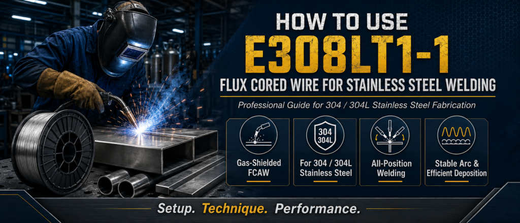
How to Use E308LT1-1 Flux Cored Wire for Stainless Steel Welding
E308LT1-1 flux cored wire is a popular filler metal for welding austenitic stainless steels such as 304 and 304L. Designed for gas-shielded flux cored arc welding, it combines continuous wire feeding with good deposition efficiency, stable welding performance, and versatile welding position capability.
For fabricators, welders, maintenance teams, and industrial users, understanding how to use E308LT1-1 flux cored wire for stainless steel welding is essential for achieving consistent weld quality.
This guide explains what E308LT1-1 is, where it is used, how to prepare the welding equipment, how to select suitable operating conditions, and how to avoid common welding problems.
What Is E308LT1-1 Flux Cored Wire?
E308LT1-1 is a gas-shielded stainless steel flux cored welding wire designed primarily for joining compatible austenitic stainless steels.
The wire has a tubular structure containing flux ingredients inside a metallic outer sheath. During welding, the wire melts continuously while the flux helps control the arc, slag formation, weld bead appearance, and overall welding performance.
Unlike self-shielded flux cored wires, E308LT1-1 requires external shielding gas during operation.
The combination of flux and shielding gas helps protect the molten weld pool from atmospheric contamination and contributes to consistent stainless steel welds.
What Stainless Steel Can E308LT1-1 Weld?
E308LT1-1 is commonly selected for welding stainless steels with compositions compatible with the 308L filler metal family.
Typical applications include:
304 stainless steel
304L stainless steel
Similar 18Cr-8Ni austenitic stainless steels
Stainless steel fabrication
Stainless steel structures
Tanks and vessels
Process equipment
Industrial machinery
Stainless steel piping components
Repair and maintenance work
For critical applications, filler metal selection should always be verified against the exact base metal grade, service temperature, corrosion environment, joint design, and applicable welding procedure.
Why Use E308LT1-1 for Stainless Steel Welding?
E308LT1-1 offers several characteristics that make it useful in industrial stainless steel fabrication.
High Welding Productivity
Because the wire is continuously fed through the welding gun, operators do not need to repeatedly stop and replace electrodes.
This can improve deposition efficiency and reduce downtime during longer welds.
Good Arc Stability
When used with suitable shielding gas and correctly adjusted welding parameters, E308LT1-1 can provide smooth and stable arc characteristics.
Stable arc behavior helps the welder maintain consistent travel speed and weld bead formation.
Versatile Welding Positions
The T1 classification is associated with welding capability beyond flat and horizontal positions, making E308LT1-1 stainless steel flux cored wire useful for fabrication where different joint orientations are encountered.
Actual approved welding positions should still be confirmed for the specific wire and welding procedure.
Suitable for 304 and 304L Stainless Steel
One of the main reasons E308LT1-1 is widely used is its compatibility with common 304-type stainless steels.
This makes it useful for a broad range of general stainless steel fabrication applications.
Efficient Slag System
Flux cored welding produces a slag layer that protects the weld bead while it cools.
With suitable welding technique, the slag can help produce a well-defined weld bead and can be removed between welding passes.
Equipment Needed for E308LT1-1 Welding
Before welding, make sure the welding system is correctly configured.
Typical equipment includes:
Constant-voltage welding power source
Wire feeder
FCAW-compatible welding gun
Correct contact tip
Suitable drive rolls
E308LT1-1 flux cored wire
Approved shielding gas
Gas regulator and flow meter
Welding ground clamp
Stainless steel cleaning tools
Welding helmet and protective equipment
The equipment must be capable of supplying the voltage and wire feed speed required for the selected wire diameter.
Step 1: Confirm the Base Material
Before loading the wire, identify the stainless steel being welded.
For many general fabrication applications involving 304 or 304L stainless steel, E308LT1-1 may be an appropriate filler metal.
However, do not choose filler metal based only on appearance.
Different stainless steel grades can require different filler metals depending on:
Chromium content
Nickel content
Molybdenum content
Carbon level
Service temperature
Corrosion conditions
Mechanical property requirements
Correct material identification is the first step toward a reliable weld.
Step 2: Prepare the Stainless Steel Surface
Cleanliness is especially important when welding stainless steel.
Before welding, remove:
Oil
Grease
Dirt
Moisture
Paint
Scale
Heavy oxide
Cutting residues
Carbon steel contamination
Use clean tools dedicated to stainless steel whenever possible.
A stainless steel wire brush should not previously have been used on carbon steel. Grinding discs and other abrasive tools should also be kept separate where contamination control is important.
Contamination can affect weld appearance and may reduce the corrosion resistance expected from stainless steel.
Step 3: Prepare the Joint
Proper joint design depends on material thickness and fabrication requirements.
Common stainless steel joints include:
Butt joints
Fillet joints
T-joints
Lap joints
Corner joints
For thicker material, beveling may be required to obtain sufficient penetration and fusion.
Make sure the joint gap, bevel angle, root face, and alignment meet the welding procedure requirements.
Poor joint preparation cannot usually be corrected simply by increasing welding current.
Step 4: Install the E308LT1-1 Wire
Install the spool of E308LT1-1 stainless steel flux cored wire on the wire feeder.
Check that the spool rotates smoothly without excessive resistance.
The wire should pass correctly through:
Wire feeder
Drive rolls
Gun liner
Contact tip
Choose drive rolls appropriate for flux cored wire.
Do not apply excessive drive-roll pressure. Too much pressure may deform the tubular wire and cause feeding problems.
At the same time, insufficient pressure can allow the wire to slip.
Adjust the feeding system until the wire moves smoothly and consistently.
Step 5: Select the Correct Contact Tip
Use a contact tip that matches the diameter of the welding wire.
A worn or incorrectly sized tip may cause:
Unstable electrical contact
Erratic wire feeding
Irregular arc behavior
Excessive spatter
Poor bead appearance
Replace damaged or heavily worn contact tips before starting important production welds.
Step 6: Connect the Shielding Gas
A major difference between E308LT1-1 and self-shielded stainless steel wires is that E308LT1-1 uses external shielding gas.
The shielding gas protects the welding arc and molten metal from atmospheric contamination.
Connect the gas cylinder to:
Regulator
Flow meter
Gas hose
Wire feeder or welding gun
Before welding, inspect the entire system for leaks.
The exact shielding gas composition and flow rate should follow the specifications for the particular E308LT1-1 wire being used.
Do not assume that every stainless steel flux cored wire uses exactly the same gas mixture.
Step 7: Verify Polarity
Correct electrical polarity is essential for stable flux cored arc welding.
Before starting production, confirm the polarity specified for the particular E308LT1-1 wire.
Incorrect polarity may result in:
Unstable arc
Excessive spatter
Poor penetration
Irregular bead profile
Difficult slag removal
Never select polarity only by habit. Follow the wire specification and qualified welding procedure.
Step 8: Set Voltage and Wire Feed Speed
Voltage and wire feed speed are two of the most important FCAW settings.
Wire feed speed has a strong influence on welding current, while voltage affects arc length and bead characteristics.
The correct settings depend on:
Wire diameter
Material thickness
Welding position
Joint design
Shielding gas
Desired penetration
Travel speed
Start within the recommended operating range for the selected E308LT1-1 wire and then fine-tune the settings based on actual arc behavior and weld quality.
Avoid using one fixed parameter set for every joint.
Step 9: Establish the Correct Wire Stick-Out
Electrode extension, often called stick-out, is the distance between the contact tip and the end of the welding wire.
Stick-out affects the electrical resistance heating of the wire and therefore influences welding current and deposition behavior.
If the stick-out is too short or too long, the result may include:
Arc instability
Excessive spatter
Poor penetration
Irregular bead shape
Inconsistent deposition
Maintain a consistent electrode extension throughout the weld and follow the recommended range for the wire being used.
Step 10: Position the Welding Gun Correctly
Gun angle affects penetration, slag behavior, bead shape, and weld visibility.
For many flux cored welding applications, the operator uses a drag or pull technique rather than pushing the gun aggressively into the weld pool.
However, the exact angle should depend on:
Joint type
Welding position
Material thickness
Weld direction
Avoid excessive gun angles.
Keeping the welding gun reasonably close to the proper work angle helps direct the arc into the joint and promotes more consistent fusion.
Step 11: Start the Arc and Maintain a Steady Travel Speed
Once the equipment is correctly set, establish the arc and maintain a stable welding motion.
The welder should focus on:
Constant travel speed
Consistent gun angle
Stable stick-out
Proper arc position
Correct weld pool size
Moving too slowly can create an excessively large weld pool, high heat input, and unnecessary bead reinforcement.
Moving too quickly may produce insufficient fusion, undercut, or an undersized weld.
A consistent travel speed is essential for uniform weld appearance.
Step 12: Control Heat Input
Stainless steel behaves differently from carbon steel during welding.
Excessive heat input can cause:
Greater distortion
Wider heat-affected zones
Excessive discoloration
Unnecessary metallurgical changes
Reduced productivity
Use the lowest practical heat input that still provides the required penetration and fusion.
Heat input can be managed by adjusting:
Current
Voltage
Travel speed
Welding sequence
Interpass temperature
Controlling heat is particularly important when welding thinner stainless steel components.
Step 13: Watch the Weld Pool and Slag
Successful FCAW requires the welder to distinguish between the molten weld metal and the slag.
The arc should remain positioned so that slag does not flow ahead of the weld pool.
If slag moves in front of the arc, it can become trapped inside the weld and contribute to slag inclusions.
Maintain an appropriate travel angle and travel speed so that the arc continues to work on clean base metal and the molten weld pool.
Step 14: Remove Slag Between Passes
E308LT1-1 is a flux cored wire, so slag forms on the weld surface.
For multipass welding, remove slag completely before depositing the next bead.
Use suitable stainless steel cleaning tools to remove:
Slag
Loose oxide
Spatter
Surface contamination
Pay particular attention to weld toes and narrow joint areas where slag can remain trapped.
Failure to clean between passes can lead to slag inclusions and poor weld integrity.
Step 15: Inspect the Finished Weld
After welding and cleaning, inspect the weld.
Look for visible indications such as:
Cracks
Undercut
Excessive reinforcement
Incomplete fill
Excessive spatter
Poor bead profile
Surface porosity
Slag inclusions
Arc strikes outside the joint
For critical fabrication, visual inspection may be supplemented by other inspection or testing methods according to the applicable quality requirements.
Recommended Welding Technique for E308LT1-1
Good technique is just as important as correct machine settings.
Several practical habits can improve results when using E308LT1-1 flux cored wire.
Maintain a Consistent Arc
Avoid unnecessary changes in stick-out or gun angle.
An unstable hand position can cause noticeable differences in penetration and bead appearance.
Avoid Excessive Weaving
Wide weaving generally increases heat input and may make slag control more difficult.
Where possible, use controlled stringer beads or moderate weaving according to the welding procedure.
Keep the Weld Pool Manageable
A very large weld pool is difficult to control, particularly in vertical or overhead welding.
Adjust wire feed speed, voltage, travel speed, and technique to maintain a manageable molten pool.
Keep Shielding Gas Coverage Stable
Avoid welding where strong air movement can disturb the shielding gas.
Fans, open doors, outdoor wind, or nearby ventilation systems can reduce gas coverage and increase the risk of porosity.
How to Weld 304 Stainless Steel With E308LT1-1
When welding 304 stainless steel with E308LT1-1, begin by confirming material compatibility and preparing the surface thoroughly.
After setting up the wire feeder and shielding gas system:
Clean the 304 stainless steel joint.
Prepare the required joint geometry.
Install E308LT1-1 wire.
Verify shielding gas.
Confirm polarity.
Set voltage and wire feed speed.
Establish proper stick-out.
Maintain the correct work and travel angle.
Weld at a consistent travel speed.
Remove slag between passes.
Inspect the completed weld.
For production welding, use a qualified welding procedure whenever required.
Welding Positions With E308LT1-1
One advantage of E308LT1-1 stainless steel flux cored wire is its ability to support welding in multiple positions when the specific product and procedure are approved for those positions.
Possible applications can include:
Flat welding
Horizontal welding
Vertical welding
Overhead welding
Position welding requires additional control of the weld pool.
For vertical or overhead work, excessive current or an overly large weld pool can make control difficult.
Operators may need to use lower deposition conditions and carefully controlled travel techniques compared with flat welding.
Common Applications of E308LT1-1
E308LT1-1 flux cored wire can be used in many stainless steel fabrication industries.
Typical applications include:
Stainless Steel Tanks
The wire can be used for compatible stainless steel tanks and containers where efficient deposition is required.
Process Equipment
304-type stainless steels are widely used in industrial process equipment, making E308LT1-1 suitable for many corresponding fabrication applications.
Food Processing Equipment
Stainless steel is frequently selected where cleanliness and corrosion resistance are important.
Welding procedures should account for the hygienic and surface-finish requirements of the final equipment.
E308LT1-1 Stainless Steel Structures
Flux cored wire can improve productivity when welding structural stainless steel components.
Maintenance and Repair
Continuous wire feeding can be useful for repair operations where multiple welds must be completed efficiently.
Piping Components
E308LT1-1 may be suitable for compatible stainless steel pipe components depending on the joint design, procedure, and applicable code.
Common E308LT1-1 Welding Problems
Even when the correct wire is selected, unsuitable welding conditions can cause defects.
E308LT1-1 Excessive Spatter
Possible causes include:
Incorrect voltage
Incorrect wire feed speed
Wrong polarity
Excessive stick-out
Poor electrical connections
Unstable wire feeding
Correct the equipment setup before changing welding technique unnecessarily.
E308LT1-1 Porosity
Possible causes include:
Insufficient shielding gas
Gas leaks
Excessive gas turbulence
Strong drafts
Dirty base metal
Moisture or contamination
Check the shielding gas system and clean the joint thoroughly.
Slag Inclusions
Possible causes include:
Slag not removed between passes
Incorrect gun angle
Poor bead placement
Excessive weaving
Low heat input
Poor joint preparation
Clean every welding pass carefully before continuing.
Lack of Fusion
Possible causes include:
Travel speed too high
Insufficient current
Incorrect gun angle
Poor joint preparation
Arc directed away from the joint
The welding arc must adequately melt both the base metal and previously deposited weld metal.
Undercut
Possible causes include:
Excessive voltage
Excessive travel speed
Incorrect gun angle
Poor technique
Adjust the welding parameters gradually and evaluate the weld bead after each change.
E308LT1-1 vs E308LT0-3
E308LT1-1 and E308LT0-3 are both stainless steel flux cored filler metals, but they are intended for different welding conditions.
E308LT1-1
E308LT1-1 is a gas-shielded flux cored wire.
Key characteristics include:
External shielding gas required
Suitable for compatible 304-type stainless steels
Flux cored productivity
Versatile welding position capability
Suitable for shop and industrial fabrication
E308LT0-3
E308LT0-3 is a self-shielded flux cored wire.
Key characteristics include:
No external shielding gas required
Greater portability
Useful for suitable field welding
Primarily associated with flat and horizontal welding
Choosing between the two depends on welding position, shielding gas availability, production requirements, and the qualified welding procedure.
E308LT1-1 vs Solid Stainless Steel Wire
Solid stainless steel wire and flux cored wire can both be used for stainless steel welding, but their operating characteristics differ.
E308LT1-1 may offer advantages such as:
Higher deposition capability
Good positional welding performance
Flux-assisted bead formation
Efficient production welding
Solid wire may provide other advantages depending on:
Material thickness
Surface finish requirements
Welding process
Production environment
The best choice depends on the specific fabrication application rather than one process being ideal for every job.
How to Store E308LT1-1 Welding Wire
Proper storage helps maintain reliable welding performance.
Store E308LT1-1 wire:
Indoors
In a clean area
In a dry environment
Away from moisture
Away from oils and chemicals
Protected from physical damage
Keep unopened wire in its original packaging until required whenever practical.
Once opened, protect the spool from dust, condensation, and contamination.
If the wire becomes visibly contaminated or damaged, do not assume it will weld normally.
How to Choose the Right E308LT1-1 Wire
Before purchasing E308LT1-1, consider several factors.
Wire Diameter
Choose the diameter based on:
Material thickness
Welding current
Joint size
Welding position
Required deposition rate
Equipment capacity
E308LT1-1 Base Metal
Confirm that E308LT1-1 is compatible with the stainless steel grade being welded.
Welding Position
If vertical or overhead welding is required, verify that the selected wire and procedure support those positions.
Shielding Gas
Confirm the required shielding gas before production starts.
Mechanical Properties
For critical fabrication, verify that deposited weld metal meets the required mechanical properties.
Corrosion Requirements
Consider the environment in which the welded component will operate.
Severe chemical, chloride-rich, high-temperature, or other demanding environments may require different stainless steel grades or filler metals.
Advantages of E308LT1-1 Flux Cored Wire
When correctly selected and applied, E308LT1-1 can provide several practical advantages:
Suitable for 304 and 304L stainless steel
Efficient continuous wire feeding
Good deposition productivity
Stable arc characteristics
Good bead appearance
Gas-shielded welding performance
Multiple-position welding capability
Suitable for industrial fabrication
Useful for repair and maintenance
Consistent performance with proper parameters
These characteristics make E308LT1-1 flux cored welding wire a practical option for many stainless steel welding operations.
E308LT1-1 Conclusion
Learning how to use E308LT1-1 flux cored wire for stainless steel welding requires more than simply loading the wire into a welding machine.
Successful welding begins with correct filler metal selection, clean stainless steel surfaces, proper joint preparation, reliable wire feeding, suitable shielding gas, correct polarity, and carefully adjusted welding parameters.
During welding, maintaining consistent stick-out, gun angle, travel speed, and weld pool control helps produce uniform results. For multipass welding, complete slag removal between passes is particularly important.
For compatible 304 and 304L stainless steel welding, E308LT1-1 offers an effective combination of gas-shielded FCAW productivity, continuous wire feeding, positional flexibility, and practical industrial performance.
When the wire is matched correctly to the base material and used according to a qualified welding procedure, E308LT1-1 can provide an efficient solution for stainless steel fabrication, maintenance, repair, tanks, process equipment, structures, and other industrial welding applications.